 International Defense Security & Technology Your trusted Source for News, Research and Analysis
Related Articles

Millimeter waves are electromagnetic signals with frequencies ranging from 30 to 300 GHz that correspond to wavelengths of 10 to 1 mm in the free space. Electromagnetic waves in the millimeter-wave band (with frequencies between 30 and 300 GHz, or wavelengths between 10 and 1.0 mm) have attractive characteristics. One of their features is the wider usable frequency band compared with waves in the microwave band or lower bands. Another feature of using the millimeter-wave band is the fact that it becomes possible to design smaller and lighter equipment that utilizes that band. So it is useful to adapt millimeter waves for short-range broadband communication systems, high resolution sensing systems and radio astronomy.
The main applications for millimeter wave systems are in communications, homeland security, imaging, radar and spectroscopic observation. Next generation wireless systems such as 5G cellular communications, front-haul and back-haul networks, military and automotive radar, and IEEE 802.11ad and 802.11ay WiGig are targeting a range of new capabilities including higher bandwidth, more connected devices, low latency, and better coverage. To address the wide bandwidth requirements, researchers are exploring the higher frequencies in the centimeter and millimeter wave bands where more spectrum is readily available.
Such signals in natural atmosphere environment are susceptible to attenuation at different rates for different wavelengths (frequencies) which makes them very useful in specific applications. The atmospheric attenuation of mm-waves is caused by gases and constituents that naturally occur in the environment. Frequencies where the average absorption of mm-waves is the lowest are called low attenuation windows and occur mainly around 35, 77 and 94, 140, 220, 340, 410, 650 and 850 GHz. The regions with highest averaged absorption levels are called attenuation lines and can be seen around 22, 60, 118, 183, 320, 380, 450, 560, 750 GHz.
It is the oxygen molecules that are responsible for high attenuation at 60, 118 and 560 and 750 GHz. The rest of the attenuation lines are caused mainly by water droplets of various diameter sizes as well as other chemical species (CO2, N2O, NO, SO2 and SH2) at submillimeter wavelengths. Due to different properties of mm-waves at different frequencies and environmental conditions the applications of mm-waves vary largely from communications, imaging and security applications, radar, radiometry and atmospheric sensing.
The mm-wave applications correlate closely with how such signals propagate in the atmosphere. The frequencies for which atmospheric attenuation is low (44, 86, 94, 140 GHz) are particularly useful in communication system operating at long ranges such as: satellite communications, backhaul mm-wave radios and point to multi-point radio links. For short range communications the 60 GHz band provides enough range where only a local area, short distance transmission is required. Other application benefiting from low atmospheric attenuation would include automotive radars at 24, 77 and 94 GHz where a long range transmission and reception is possible.
Imaging and security utilizes a mixture of high and low attenuations bands for passive and active systems. These use 77, 94 and 183 GHz frequencies as these signals present good properties to penetrate many materials (i.e. clothing) and see through the fog and rain. For those materials that can not be penetrated the atmospheric environment provides a good thermal contrast from which images can be synthesized at post processing level.
A cornerstone in the ability to achieve self-driving vehicles is the ability to detect and avoid obstacles. Millimeter wave radar technology is advancing rapidly to support the array of sensors needed. Automotive Radar Frequency Bands are 24, 77, and 79 GHz. Consumer WiFi applications have expanded beyond what is available from 802.11ac devices. The designation 802.11ad is an extension of the IEEE’s popular 802.11 family of wireless local-area network (LAN) standards. The 58 to 64 GHz spectrum has long been available for unlicensed services, and was recently expanded up to 71 GHz (FCC Part 15). Examples of applications are high-speed wireless multimedia services, including uncompressed high-definition TV (HDTV) and instantaneous music and image data transmissions.

5G NR will require much faster data rates in order to support enhanced mobile broadband (eMBB) use cases like UHD video streaming, virtual reality (VR), and augmented reality (AR). As mobile operators accelerate their 5G NR deployment plans, chipset and device manufacturers must also accelerate their development activities, including determining how to test 5G NR data throughput most effectively.
The 5G eMBB (enhanced mobile broadband) use case targets data rates of up to 20 Gbps in the downlink (DL) and 10 Gbps in the uplink (UL). 5G NR accomplishes this by utilizing higher-frequency mmWave spectrum, in addition to using sub-6 GHz frequencies.
The 5G networks will employ a broad range of spectrum frequencies, including the popular 28 GHz and 39 GHz 5G mmWave bands. Here it’s worth noting that while LTE will be an integral part of 5G networks, the role of mmWave frequencies is likely to grow due to the availability of plentiful spectrum as well as aggregated channel bandwidth of 1 GHz and higher.
MmWave challenges
At the same time, however, 5G mmWave frequencies will require more sophisticated test solutions for chipsets, mobile devices, network infrastructures and cybersecurity. That’s because these airwaves travel at shorter distances and are more susceptible to radio propagation loss issues. Then, there are propagation loss issues at higher mmWave frequencies, where signal power can quickly diminish due to environmental conditions like rain or snow.
At millimeter-wave (mmWave) frequencies, excessive path loss makes RF power limited and costly. The mmWave frequencies demand more sophisticated RF parametric measurements for signal gain, directivity, beamwidth and antenna efficiency. These RF parametric measurements become even more challenging because of 5G’s smaller device size and array size. Any skew in a flange connection can cause unwanted reflections that degrade signal quality and power.
The antenna is especially a sensitive area in mmWave frequencies because of the phase arrays and the need for greater accuracy in gain measurements. Therefore, the use of smart adaptive antennas in phase arrays poses additional test challenges. Moreover, while 4G LTE terminal devices like smartphones have several built-in antennas, those for 5G will have a significantly higher number of antennas. Having a measurement connector for each antenna could cause problems for test engineers, especially when the size of mobile devices is continuously shrinking. In fact, many 5G components do not even have connectors, and therefore, cannot be tested in conducted setups.
Another critical issue in 5G device radio performance testing and validation is the diverse deployment of radio spectrums. For now, 28 GHz and 39 GHz 5G millimeter wave bands are the most popular, but eventually 5G networks could employ mmWave frequencies ranging from 26.5 GHz to 67 GHz. Therefore, the test solution must provide far field radio characterization capabilities — gain, directivity, beamwidth, 3D radiation pattern and antenna efficiency — across a broad range of mmWave frequencies.
The field trials for 5G mmWave radios have already started generating and analyzing frequency bands of up to 40 GHz. And what has been discovered here is that measuring the parameters, like signal profile, range and capacity for higher-gain antennas steering more powerful beam signals in mmWave communications, is far more challenging than LTE testing.
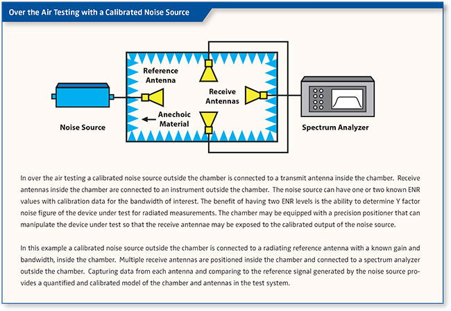
Also, the components designed for mmWave devices are compact and highly integrated with no place to probe, resulting in the need for radiated tests, also known as over-the-air (OTA) tests.
What is also apparent is that the 5G systems are using more system-in-package implementations, which means that testing will happen both at the component and system levels. Therefore, packaging technology advancements must align with the over-the-air (OTA) test methodologies to create more repeatable test procedures and thus keep the overall test cost in control.
Take, for instance, 5G transceivers, which in many cases need to be tested in conjunction with the antennas. The 5G designs are increasingly implementing system-in-package solutions, which means that antennas also come integrated with an RF front-end module (FEM) and transceivers. Therefore, what is really needed is a flexible hardware platform that can be modified by adding or removing modules to test a wide range of 5G devices, channels and network configurations. For example, test engineers can use the same test system to prototype different mmWave bands with the same intermediate frequency (IF) and baseband hardware and software.
The excessive path loss at millimeter-wave frequencies between instruments and devices under test (DUTs) results in a lower signal-to-noise ratio (SNR) for signal analysis. Lower SNR makes transmitter measurements challenging, such as error vector magnitude (EVM), adjacent channel power (ACP), and spurious emissions. Engineers typically reduce the attenuation of the signal analyzer to improve the SNR. However, even when the input attenuation is set to 0 dB, the SNR can still be too low for accurate signal analysis. So, minimizing any possible path loss is critical for millimeter-wave testing.
Millimeter Wave Test Parameters and Specifications
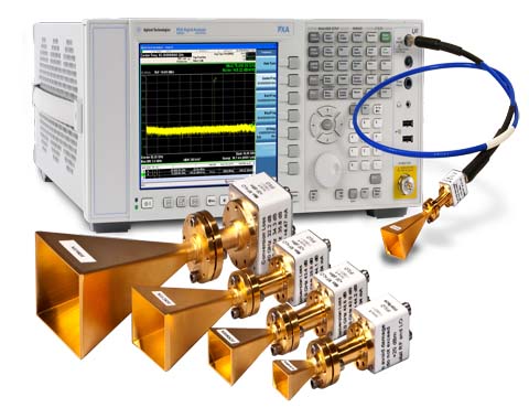
All the applications mentioned, at some stage of their development, need to employ a mm-wave measurement system for component and system level testing and evaluation. Most millimeter wave applications employ millimeter wave measurement systems to verify device specifications. These measurement systems utilize microwave instrumentation and external up/down converters to perform the required tests.
Millimeter Wave Test Parameters and Specifications are strong functions of the specific application. However, the following are basic specifications for most applications: Frequency: Transmit and/or Receive; Bandwidth: Transmit and/or Receive; Modulation; Power Transmit (min/max), Receive (min/max); Distance/Resolution; Antenna or Beam Width; Update Rate; Mechanical dimension and weight; Power Supply (voltage, current, and DC power consumption); Interface; Cost; and Technology Used.
Millimeter wave applications can be used in one of four modes: 1). CW mode, 2). Modulated CW mode, 3). Pulsed RF mode, and 4). Pulsed RF and pulsed bias modes. The number of ports could vary from two ports to multiports (4, 5, 6…) and could be single ended or differential. Most millimeter wave applications have a very small bandwidth of < 1 GHz. Signals transmitted and/or received can be modulated in scalar or vector techniques. The modulation bandwidth is much smaller than the application bandwidth, usually 10-100 MHz.
Millimeter wave measurements could be displayed in three different domains: time, frequency or modulation. Most millimeter wave measurement systems use the frequency domain, and then convert to time domain, if needed. Millimeter wave measurements can be divided into three ranges: 1). In band, 2). Out of band, and 3). In band harmonic.
Millimeter Wave Instrumentation
Most commonly purchased and used test and measurements instruments operate below 20 GHz. Such operating range is adequate to fulfill the evaluation and test purposes in most cases. However with the advent of mm-wave applications, more so than ever before, there is a need for measurement systems operating at frequencies above 20 GHz and very often beyond 110 GHz. Such systems in principle are thought to extend the range of standard instruments beyond their range by means of frequency multiplication or mixing.
Measurement systems are determined by types of millimeter wave applications and specifications. In general there are 4 groups of test and measurement equipment commonly used in component and system evaluation by engineers: signal generators (scalar or vector), signal analyzers (scalar or vector), network analyzers (scalar or vector) and power meters. For specific applications, noise figure analyzers and/or phase noise systems are required.
Signal Generators
Modern test laboratories require high stablility signal sources that can be applied as local scillators in mixer applications or as an RF sources in antenna and receiver applications. Also mm-wave on wafer device testing requires a repeatable, as well as compact, extension source that can be easily mounted on wafer probing station positioners close to a DUT reducing therefore unnecessary losses associated with long cables at high frequencies.
New considerations for signal generation need to be made when working in millimeter wave bands. Errors like phase noise, IQ, and frequency response errors can be worse at millimeter wave and need to be addressed in order to ensure that researchers can make full use of this wideband technology. The possibility to generate a very high quality signal with a low error vector magnitude (EVM) and with low spurious content is fundamental to guarantee that the system under test performs as expected
In most cases the mm-wave users already own a microwave signal generators that are capable of supplying frequencies up to 20 GHz. Frequency Extension Sources (FES) are used for extending the coverage of microwave signal sources. These modules operate on the principle of frequency multiplication and amplification.
The mm-wave signals are created with either multiplying or mixing lower frequency signals (<30 GHz). This is achieved by using active (requiring DC biasing) MMIC based multipliers or mixers at the lower end of mm-wave band (<80 GHz typically) and devices built with Schottky diode devices for higher end of mm-wave spectrum.
For scalar measurements and modulation the frequency extension can be achieved by a frequency multiplication. The generator is used as a driver for a amplifier-multiplier chain where the input signal is firstly multiplied and then amplified by an active MMIC module and used internally to drive a stand alone passive multiplier – usually a doubler or a tripler.
To reach the higher end of mm-wave spectrum a chain of passive multipliers might have to be used to achieve best output power and frequency coverage. To reach frequencies beyond 110 GHz harmonic mixers (mixers utilizing a n-th harmonic of the LO signal) or chain of multipliers (lower frequency modules driving the input of higher frequency ones – i.e. a doubler driving a tripler) are most commonly used. Due to conversion efficiency constraints in general those devices would be limited to doublers and triplers only.
Measuring Millimeter-Wave Frequencies
Frequency is an important parameter in any wireless application to be measured with dead-on precision in order to comply with the spectrum regulations you are operating under. In applications like electronic warfare (EW), you absolutely have to know the frequency of a radar, jamming, or communications signal frequency, and you need to know it immediately so action can be taken.
The most obvious frequency measurement method is to use a commercial bench frequency counter. Multiple vendors have these, and you can measure frequencies out to about 60 GHz in most cases. These counters simply open a gate for a precise interval and count the pulses that occur. The frequency is the ratio of the number of pulses counted to the gate time. For the very high frequencies, the counter may use a pre-scaler or downconverter/mixer to translate the high input frequency signal down to an IF within the range of the counter.
You can also measure frequency on a spectrum analyzer. Its horizontal scale is calibrated so a reasonable measurement can be made. Such measurements are useful for finding harmonics, intermodulation distortion products, and interfering signals, but the precision just isn’t there. In EW applications like radar, jamming, and communications, frequency needs to be measured as fast and as precisely as possible. One good technique is called instantaneous frequency measurement (IFM). Special IFM receivers are used in all forms of EW equipment.
IFM receivers use analog frequency discriminators (AFD) or digital frequency discriminators (DFD) to measure signals fast. An AFD uses the interferometer method to measure frequency. The signal is divided into two equal parts: One signal is passed through a fixed reference delay line and the other is sent through another delay line. The delay lines are phase shifters whose time delays are related to the signal frequency. The phase shifters are usually microstrip lines. The phase shifter outputs are compared and the phase difference between them is a measure of the frequency. A Schottky diode translates this difference signal to DC for measurement.
Power Meters
Microwave power is measured using power meters with power sensors. At millimeter-wave frequencies, a sensor is required to be connected and calibrated to a power meter to display the millimeter-wave power. There are commercial power meters and sensors up to 110 GHz with traceability and verification paths. Above 110 GHz, there is some progress in measuring power using sensors in these millimeter wave bands. More progress is needed in this area to measure millimeter-wave power up to 325 GHz with a traceability path.
Signal Analyzers
It is very common for microwave and millimeter wave measurements to require signal analysis on the receiver end of the measurement setup. With mm-wave applications regardless of whether a scalar or vector measurement is required the mixer plays a very important function. In both cases it is used to downconvert an incoming high frequency RF signal to an intermediate signal that is within the bandwidth of the instrument used

For scalar analysis measurements, harmonic mixers are used to down convert the millimeter wave signal into the IF of microwave signal analyzers. There are a wide variety of makes and types of spectrum analyzers available from instrument makers such as Agilent, Rohde & Schwarz, Tektronix, Advantest and Anritsu to name just a few.
Due to their balanced configuration all the mixers operate on even LO harmonics without a need of a bias. The mixer is connected to the analyzer with a flexible cable and its operation setup is fully visible to the user through the instrument interface. Its frequency range (waveguide type) and conversion loss can be setup in the analyzer for accurate measurements. The analyzer uses the external mixer as a part of its own receiver circuit. The LO harmonic number, RF frequency range with its corresponding conversion loss values can be loaded up onto the instrument from the data supplied with the harmonic mixer. That way the actual display of the instrument will reflect the actual results in a real time manner.
Many spectrum analyzers offer an option to use an external mixer where the analyzer provides LO signal for the mixers and the IF output of the mixer is connected to the analyzer signal input. That way the effective range of the instrument is extended to the range of the harmonic mixer.
Use external mixing — extending frequency ranges and measurement plane
When you build a millimeter-wave test system, cables and accessories in the path between the signal analyzer and the DUT increase insertion loss. Adding an external mixer is a cost-effective way to extend the frequency range of a signal analyzer and move the test plane close to the DUT to reduce insertion loss caused by the long millimeter-wave signal routing.
Harmonic mixer
Signal analyzers send a microwave local oscillator (LO) signal to an external mixer and receive an intermediate frequency (IF) signal from the mixer through the same cable. The analyzer further processes the IF signal with filtering, digitizing, analysis, and display operations similar to those for internal mixed signals.
External mixing provides a cost-effective solution for millimeter-wave signal analysis and moves the test port close to the DUT. However, there is no preselector at the front end of the mixer. Strong out-of-band signals may lead to unwanted images in the band of interest and degrade measurement accuracy.
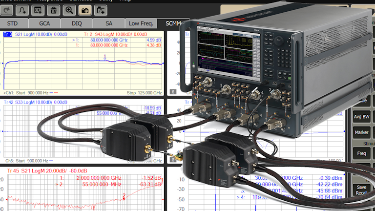
Frequency extender
An advanced external frequency extender integrates a preselector and an RF switch into a high-dynamic-range mixer with the seamless operation interface of the signal analyzer. This solution enables unbanded and preselected swept power spectrum from 2 Hz to 110 GHz without managing band breaks and images, and the RF bandwidth up to 4 GHz. Figure shows the test setups for a signal analyzer and an external frequency extender.

Network Analyzers
For scalar network analyzers, detectors are used to capture the magnitude of millimeter wave signals. Once the DC voltage is delivered to the network analyzer the display is shown using the same signal processing as in RF or microwave frequencies. Thus, the appropriate detector must be found to establish a complete scalar network analyzer to cover the appropriate waveguide band.
Vector Analyzer
The vector network analyzer is different because the signal phase needs to be determined and calibrated at the DUT’s millimeter wave frequencies. Multiplying the microwave signal from below 20 GHz to the millimeter wave band is the first step. The incident and reflected waves are down converted using a dual directional coupler and two harmonic mixers. These signals are connected to the vector network analyzer’s IF input. Calibration is done at the millimeter wave band using standard TRL, OSLT, LRM or any other calibration technique. For each waveguide band there exists a unique calibration hardware kit. At the present time, there are commercial vector network analyzers that measure up to 325 GHz. Two types of millimeter wave vector network analyzers are CW and pulsed. Depending on the pulse width and repetition rate, one specific type of analyzer is more suitable than others. The pulsed bias technique is used to test high power DUTs at the wafer level to avoid device self heating

The S-parameters characterization at RF and microwave frequencies is readily available in most vector network analyzers (VNA) available on the market at present. To extend the range of microwave VNAs one must use frequency extension modules that utilize both multiplier as well as harmonic mixer technologies. Mm-wave S-parameters measurements are necessary where material characterization, on wafer measurement and research in communication, imaging and security are of interest.
Noise Figure Analyzers
Modern receiving systems must often process very weak signals, but the noise added by the system components tends to obscure those very weak signals. Sensitivity, bit error rate (BER) and noise figure are system parameters to characterize the ability of a system to process low-level signals. Noise Figure is especially significant in the fact that not only is it suitable for characterizing the entire system but also the system components such as pre-amplifiers, mixers & IF amplifiers. By controlling the noise figure & gain of the system components, it is possible to directly control the noise figure of the overall system. With this in mind it is essential for designers (component & systems) to be able to measure the performance of the receiver front end components.


To measure the noise figure of DUTs at microwave frequencies, the Y-factor technique is used with a noise source. Noise figure and gain can be displayed up to 26.5 GHz. Noise sources are available up to 50 GHz.
Phase Noise Systems
Similar to microwave phase noise measurements, a mixer is needed to down convert the millimeter wave signal to DC and then measure the phase noise.
Millimeter Wave Test Trade Offs
Calibration is required for vector network analyzers, vector signal generators, and vector signal analyzers. At millimeter wave frequencies, the calibration is critical to accomplish highly accurate measurements. Slower sweep or larger numbers of points are also important for accurate measurements. The noise floor of the test instrumentation needs to be at least 10-15 dB better than the DUT noise floor.
Similarly, the maximum input power (or output power from the DUT) should not generate any harmonic distortion of the test instrumentation. Overall, the measurement dynamic range of the measurement instrumentation should be 20 dB higher than the DUT dynamic range. Measurement uncertainty should also be calculated for any measurement system. Usually better measurement uncertainty requires more averaging or lower IF resolution bandwidth. This leads to longer measurement time.
Field Testing Issues
Spectrum analyzer measurements are often used to measure path loss of a proposed wireless link. A test source with antenna and spectrum analyzer with antenna are placed at realistic locations. At millimeter wave frequencies long cable runs can result in in significant loss. At lower frequencies, a bench instrument on a cart with the antenna elevated on a pole fed with coax cable would be used. But at 70 GHz a 3 meter cable would have over 20 dB loss, significantly reducing the measurement range and accuracy. Also, the loss and phase characteristics of cables vary with temperature adding to the uncertainty.
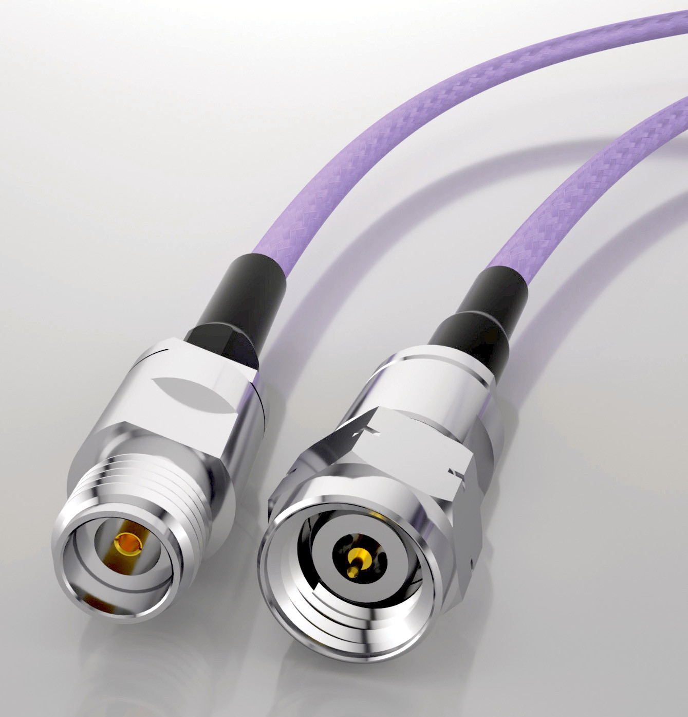
Connector technology
At 70 GHz the diameter of the coax center connector is just 1/2 mm (20 thousandths of an inch). A center pin diameter is also just 20 thousandths of an inch. Scratches and dust particles on the connector interface are more damaging to the impedance match at millimeter wave frequencies, and connector dimensions are approaching the limits of machine shops. As a result, millimeter wave connections require significantly more care. Connector interfaces should be inspected with a microscope and cleaned before each use. Connectors should be tightened with a torque wrench to the proper specification. (8 in-lbs max).
Reducing the number of connections in a test system reduces the number of points of failure (measurement error) due to dust / dirt damaging the return loss of a connection. It also minimizes the chance for imperfections to cause test system impedance variation from 50 ohms. Each connection in the system (male to female connector pair) will add uncertainty. Millimeter wave connectors and cables must be handled carefully to insure accurate measurements
Rectangular waveguide due to its inherently low loss properties is the medium that is most frequently used in mm-wave applications. Under normal conditions the electromagnetic field propagates through the waveguide in transverse electrical dominant mode TE10 and has a cut off point below which it does not propagate in any form or mode.
Measure as close to the DUT as possible
Precision, low-loss cables can be used to improve system performance. A 2 foot long precision test cable will typically cost more than a thousand of dollars and will still add uncertainty from mismatch and insertion lost. The issue of cable loss gets more complicated if multiple cables are used in a system and one tries to use a fixed set of values to correct all measurements for loss. For example; if one cable has 5 dB of insertion loss at 30 GHz and 8 dB at 70 GHz and the second cable, from the same manufacturer, has 5 dB of insertion loss at 30 GHz but 10 dB at 70 GHz it will be difficult to know what the net loss is.
In order to properly characterize and remove the impact of the cables, a network analyzer can be used to characterize each cable to know the net cable loss at each measurement frequency. This, however, can be complicated, time consuming, and costly. The only way to simply and completely remove the impact of cables is to remove the cables altogether and take measurements directly at the DUT. In this case, direct connecting the spectrum analyzer to the DUT would improve the sensitivity by 5 dB and reduce measurement uncertainty by approximately +-0.4 dB.
mmWave Transceiver System
The mmWave Transceiver System, based on the software-defined radio (SDR) technology, is a test platform that National Instruments (NI) introduced for 5G and other advanced wireless communication systems in 2016. It operates as an over-the-air communication system for a variety of 5G applications, ranging from channel sounding to MIMO link measurement.
This open communication prototype overcomes the complexity of processing multi-gigahertz channels by providing an mmWave physical layer in the source code that encompasses the fundamental aspects of the mmWave baseband subsystem. Furthermore, the software in the mmWave Transceiver System is open to developers for modifications in different design iterations. That allows developers to modify the source code for a wide range of applications such as channel sounding, 5G NR algorithm development and optimization and beamsteering algorithm testing.
Now NI has unveiled two new mmWave radio heads for connecting RF components to IF modules that convert signals to 12 GHz in the mmWave Transceiver System. These radio heads — targeted at prototyping NR 5G systems operating at 24.5 GHz to 33.4 GHz and 37 GHz to 43.5 GHz frequency bands — are compatible with the previously released mmWave radio heads. The physical layer provided in the source code is created using NI’s LabVIEW software and is compatible with the Verizon 5G TF specification and Release 15 of 3GPP’s 5G NR specifications.
References and Resources also include:
https://www.farran.com/application-notes&rdDF=Mmwave-Frequency-Extenders-article.pdf/
https://blogs.keysight.com/blogs/tech/rfmw.entry.html/2021/04/06/every_loss_countsin-0Rr1.html