International Defense Security & Technology Your trusted Source for News, Research and Analysis
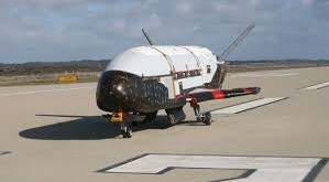
As of May 2021, there are about 4,300 active artificial satellites currently orbit Earth. We rely so much on satellites for so many things in our lives, and we count on them to be durable and reliable. When satellites don’t work properly, they can severely impact our lives. That’s why it’s so necessary to test each satellite properly before it gets launched into space. It’s also vital to test satellites properly because they are so expensive. Governments or private companies that spend millions or even billions of dollars a year on satellite technology need to know their investments will not evaporate because the satellite failed during or the following launch.
Space puts all materials under severe stress, allowing only the most robust products to survive. First, Satellite must survive the extreme vibrations and acoustic levels of the launch. Then, while in operation it has to operate in very harsh conditions. It must function in an almost complete vacuum while handling high levels of electro-radiation and fluctuation in temperatures that range from the hottest to the coldest.
Currently, NASA and some other private companies are exploring the idea of building smaller vehicles that could be capable of repairing satellites. Other ideas include assembling satellites in space. However, for now, once satellites are in orbit, they’re normally beyond the reach of repair.
Therefore, it’s required to test every satellite before it goes into orbit. Without testing, the efforts of putting satellites into orbit are for naught when the devices fail in the heat of the atmosphere or the cold of space. Satellite manufacturers must create a reliable product that supports these critical functions. Testing ensures that the final product will achieve its intended purpose while in Earth’s orbit. That is why companies that design and test satellites must consider every contingency, and examine everything that can possibly go wrong multiple times. Even if part of the satellite fails after launch, that does not mean the entire unit will get abandoned. If other components that are providing critical information are still operational, the satellite will remain in use until it has reached the end of its lifecycle.
Testing must begin at the initial phase of construction with each component. As these parts get assembled into larger pieces, they must undergo additional tests. Finally, once the final phases of satellite construction conclude, the entire unit needs to undergo rigorous testing.
Once a satellite is fully assembled, the I&T team begins a series of rigorous environmental stress tests. Collectively, these tests are designed to prove (1) that the satellite can survive the extreme acoustic and vibration environment of launch, (2) that it can sustain the explosive shock associated with separation from the launch vehicle, and (3) that once on orbit, its electronic subsystems can operate successfully in the extreme temperature and radiation environments of space.
A key satellite test procedure in qualifying a satellite for launch is swept sine testing — a variety of vibration test that uses a single frequency to test a specific structure within the satellite. During a swept sine test, the sine tone ranges up and down through various frequencies, and always for a specified rate of vibration and duration.
Recording all this data is one of the most essential parts of satellite testing. Scientists can monitor and collect all the various channels of sine data at once when a satellite is undergoing vibration testing. This data will provide the satellite testing team with clues about the construction of the satellite and whether there are any weak spots that pose a potential problem during launch.
Satellite testing presents unique challenges. Unlike testing in the automobile industry or the appliance industry, you don’t get to test a prototype before constructing the final version. When you test a satellite, you are often testing the one that will eventually go into orbit. Therefore, while the tests need to be meticulous, the testing itself cannot damage the satellite in any way.
ISO/DIS 19683(en) Space systems — Design qualification and acceptance tests of small spacecraft and units
There is an increasing demand of small/micro/nano/pico satellite development and utilization worldwide. There is no clear definition of “small”, “micro”, “nano”, or “pico” satellites that is agreeable worldwide. However, those satellites are often built with emphasis on low-cost and fast-delivery. They are characterized by extensive use of non-space-qualified commercial-off-the-shelf units. There is growing utilization of miniaturized satellites for military and defense applications. Defense organizations have been launching communication nanosatellites and microsatellites to provide communication signals to soldiers stationed in remote locations or in dense forests.
A small spacecraft is a satellite that utilizes untraditional risk-taking development and management approaches to achieve low-cost and fast-delivery with a small number of team. The satellite size is small merely as a result of seeking low-cost and fast delivery. To achieve these two points, the satellite design relies on the use of non-space-qualified commercial-off-the-shelf (COTS) units and the satellite size inherently becomes smaller. The design accepts a certain level of risk associated with the use of COTS.
This standard provides test methods and test requirements for design qualification and/or acceptance of small spacecraft or units. This standard describes minimum test requirements and test methods to qualify the design and manufacturing methods of commercial small spacecraft and their units, and to accept the final products. This standard places emphasis on achieving reliability against infant mortality after satellite launch to orbit while maintaining low-cost and fast-delivery.
Normative references
The following referenced documents are indispensable for the application of this document. For dated references, only the edition cited applies. For undated references, the latest edition of the referenced document (including any amendments) applies.
ISO 15864, Space systems — General test methods for space craft, subsystems and units
ISO 17566, Space systems — General test documentation
ISO 10795, Space systems — Programme management and quality — Vocabulary
ISO 14302, Space systems — Electromagnetic compatibility requirements
ISO 11221, Space systems — Space solar panels — Spacecraft charging induced electrostatic discharge test methods
ISO 26869, Space systems — Small-auxiliary-spacecraft (SASC)-to- launch- vehicle interface control document
ISO 14620-1, Space systems — Safety requirements — Part 1: System safety
ISO 24113, Space systems — Space debris mitigation requirements
ISO 17770, Space systems — CubeSats
ISO 20991, Space systems — Requirements for small spacecraft
Satellite Test Facilities
Satellite Test Facilities address the need for a comprehensive set of satellite test capabilities. When the satellite arrives at the testing facility after its construction, it must get unpacked in a clean room as many of the satellite tests must take place in a clean-room environment. Scientists and engineers walking around in white “bunny suits,” play an essential role in the testing process. That’s because it only takes one tiny outside contaminant to have a drastic effect on a satellite. The satellite’s assembly team is the first group to test it. Next, a quality control team must conduct a separate series of tests before declaring the satellite ready for flight. The teams often repeat many of these tests to gather enough data to decide whether or not the satellite is ready to go into orbit.
Companies like NTS maintain a network of facilities across the United States to conduct the necessary tests, including building gigantic climate chambers to analyze how a satellite responds to the vacuum of space or to extreme changes in temperature. Other centers may conduct tests for vibration, solar radiation, dealing with the dust of space or with pyroshock, which might occur during the booster separation stage or the satellite separation stage from explosive bolts. The explosive shock of booster seperation can damage circuits, dislodge contaminants in the satellite or short-circuit electrical components.
In other facilities, such as the NTS satellite testing facility in Santa Clarita, Calif., satellites get tested in a 5,000-cubic-foot acoustic chamber to learn about how the satellite reacts to heavy vibration, as well as the deafening noise of a launch. Because these tests are so rigorous — and costly to carry out — they are among the most crucial checks to conduct. The facilities needed to test satellites adequately can be enormous. For instance, the Santa Clarita facilities cover more than 150 acres.
The typical real life testing example is National Oceans and Atmospheric Administration tested its Geostationary Operational Environmental Satellite-S (GOES-S) in March 2017, ahead of its launch a year later under the new name of GOES-17. As part of that testing, the team placed GOES-S in a thermal vacuum chamber to determine its ability to operate in the extreme cold of space.
The vacuum chamber tested the satellite across four different cycles that ranged from intense cold to intense heat. Severe temperature fluctuations in the airless vacuum chamber gave scientists a chance to check how the satellite’s sensitive instruments performed in these harsh conditions. Satellites also need to get tested for shielding against external radio signals. The testing team must ensure the satellite’s antennas unfold properly and are compatible with the satellite’s other systems, as well.
Additional tests will include measurements to learn each satellite’s exact center of gravity and mass, which will ensure the satellite is compatible with its launch vehicle. It also helps control the orientation when the satellites are in orbit, which can lengthen how long they will operate in space. Scientists will need to test satellite thrusters, too, which will help orient its orbit after its launch vehicle releases it.
UK National Satellite Test Facility
UK Government is investing £105 million to establish the National Satellite Test Facility and RAL Space is overseeing the investment through the construction programme and the procurement of the specialist equipment which will be installed in the facility. The National Satellite Test Facility (NSTF) will support the assembly, integration, and testing of space payloads and satellites weighing up to seven tonnes.
The new facility will compete with the other three large-scale satellite test facilities in Europe: ESA’s European Space Research and Technology Centre (ESTEC) in Noordwijk, the Netherlands; the Intespace Test Center in Toulouse, owned jointly by Airbus and Thales Alenia Space; and the IABG test center in Munich, Germany.
Large satellite preparation and solar array deployment
Large clean rooms and associated electrical and mechanical ground support equipment will support the preparation and checking of satellites before and between tests. These rooms will also be used for solar array deployment tests and satellite integration.
Centre of gravity and moments of inertia
This facility can be used to measure a satellite’s mass properties, as well as moments of inertia and products of inertia, to ensure that it is consistent with its design parameters.
Vibration and pyro-shock
To simulate the stresses of a launch sequence, the vibration test facility will vibrate satellites in 3 axes over a frequency range of 5 to 100 Hz and acceleration levels up to +/-1.5 g.
The pyro-shock tests simulate separation of the satellite from the launch vehicle adapter.
Acoustic testing
This test facility will simulate the acoustic environment experienced by the satellite inside the delivery rocket during the initial seconds of a launch sequence. Noise levels inside the facility will typically reach 146 dBA with a frequency content range of 30 Hz to 10,000 Hz.
Large space test chamber
A bespoke 7m diameter by 12m long thermal vacuum chamber will simulate the vacuum and thermal conditions in space. It will consist of a cylindrical vacuum vessel lined with temperature controlled panels. The Large Space Test Chamber will test spacecraft for the harsh conditions of space including extreme temperatures from -180°C to +100°C. UK and international businesses will be able to test spacecraft up to the size of a minibus as well as fleets of shoebox-size satellites supporting the growth of the UK’s £14.8 billion sector.
Weighing more than 98 tonnes in total, the chamber was transported in sections on 6 lorries accompanied by 6 police outriders and 5 support vehicles. The convoy from Portsmouth Harbour to Harwell Campus was one of the largest single road movements the UK has ever seen.
Large Space Test Chamber facts and figures:
- Internal dimensions: 7m x 12m – big enough to test a 7 tonne, minibus-size satellite
- External dimensions: 8m x 16m
- Total weight: 98 tonnes
- Temperature range 95K to 373K (-180°C to +100°C)
The enormous chamber will be used by the space industry to test spacecraft up to 7 tonnes for the harsh conditions of space. The chamber can be heated and cooled using nitrogen cooled shroud panels to achieve a temperature range of 95 Kelvin to 373 Kelvin to (-180°C to +100°C) so that satellites can be tested for missions into the chill of deep space or near to the Sun. It will be operated by STFC’s RAL Space, and alongside other test equipment at the National Satellite Test Facility will enable UK businesses to bid competitively for new contracts and remain a world leader in space technologies.
Each of the 8m diameter sections then had to be lifted into place and carefully positioned in order to be sealed perfectly later in the year. The final walls of the building will now be constructed around the chamber.
Electromagnetic compatibility and antenna test
An electrically clean environment will allow satellite electromagnetic emissions to be accurately measured. It will contain a planar near-field scanner to measure the performance of antennas used for communications between the satellite and ground stations.
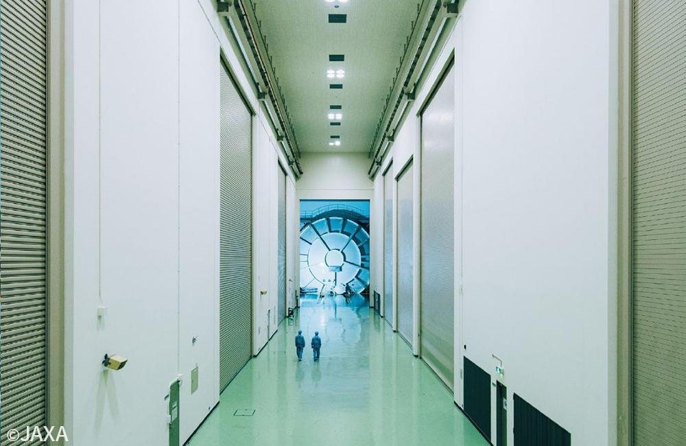
Environmental Test Facility Operation and Utilization Expanding Project Starts in JAXA Tsukuba Space Center Through Public-Private Partnership
The Japan Aerospace Exploration Agency (JAXA), working in collaboration with Advanced Engineering Services Co., Ltd. (AES), and ORIX Rentec Corporation, launched an environmental test facility operation and utilization expanding project. This project is intended to promote the efficient maintenance and operation of the environmental test facilities at JAXA’s Tsukuba Space Center as well as expanding the use of these facilities beyond space development to include other industries. This is JAXA’s first facility operation and use expansion project undertaken through a public-private partnership.
Spacecraft undergo various environmental testing before launch to ensure that they can function properly under the sever conditions of outer space including vibration, vacuum, and extremely low temperatures. The Tsukuba Space Center owns Japan’s largest environmental test facilities including space chambers for performing thermal vacuum testing of spacecraft and a large vibration test facility. These facilities and JAXA’s technologies support development in the aerospace field.
In recent years, small satellite startups as well as companies from outside the space industry, such as automobile and construction companies, have been actively entering the space business, and demand for environmental testing is increasing. High levels of capital investment and advanced technological capabilities are needed, however, creating barriers to entry by small businesses and companies from other industries. In addition, when companies outside the space industry conduct environmental testing as a part of their product development, insufficient facility performance, competition in scheduling, and other issues have become increasing serious with respect to in-house test facilities and sites as a result of the diversification of products, the increasing pace of development, and other factors, and there is a need for facilities with advanced testing capacity and facilities that can meet the demand for special testing.
JAXA concluded a business agreement with AES and granted operating rights to test equipment and facilities as well as the sites peripheral to the facilities. AES and ORIX Rentec formed a business tie-up, and the three parties will collaborate with the aim of expanding use of environmental test and other facilities by companies in other industries. JAXA will provide 18 environmental test facilities, 10 buildings, and the Tsukuba Space Center site, while AES, which has technologies acquired through space development, will be responsible for the operation of the environmental test facilities and technical support for environmental testing. ORIX Rentec, Japan’s first electronic measuring instrument rental company, has a nationwide sales network and will conduct sales activities in order to expand utilization and develop plans and proposals for using the site.
Examples of Facilities Available for Use
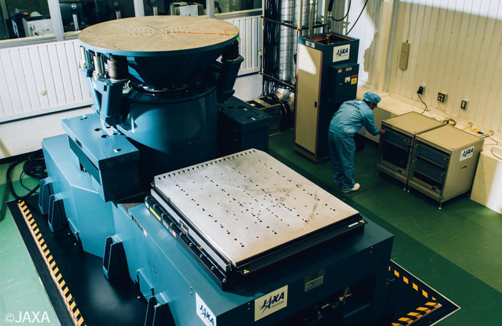 |
Vibration Test FacilityFour types of vibration machines can be selected according to the size and use of the test item. Acceleration sensors are also available for loan. |
|---|
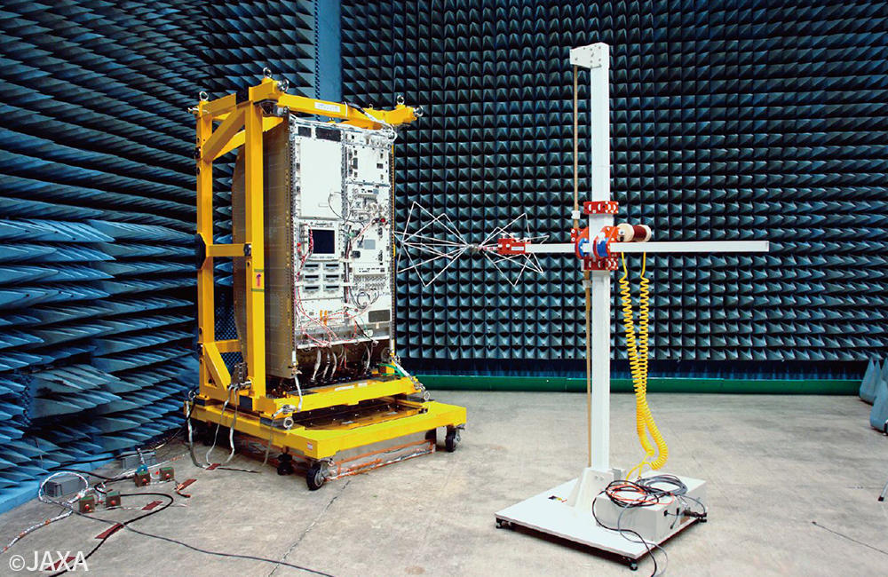 |
EMC and Radiowave Test FacilityThree anechoic chambers can be used for EMC assessment, antenna assessment, and other testing depending on the application. |
|---|
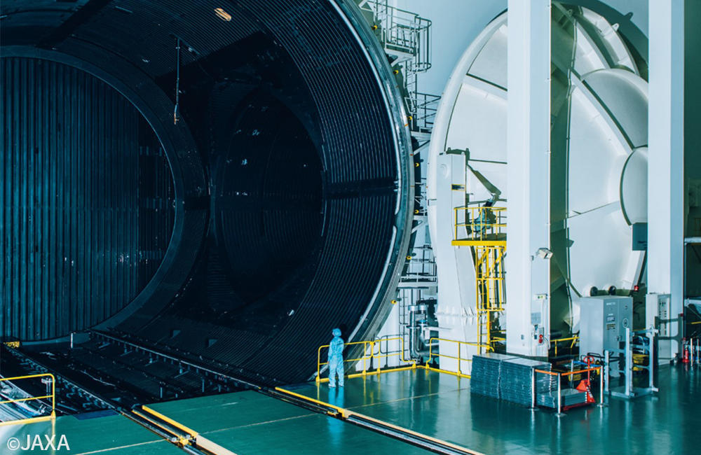 |
Space ChambersThese facilities allow the creation of a vacuum and low-temperature environment inside the chambers. Five different sized chambers can be selected according to the size required. |
|---|
 |
Clean Rooms and Meeting RoomsThe site has multiple clean rooms with controlled temperature and humidity. An area with a ceiling height of 18 m can be used for large structures that require a high degree of cleanliness and use for drone flight testing and other such applications is also under consideration. Overhead cranes for heavy objects, measuring instruments, and meetings rooms of various sizes are also available. |
|---|
Active Thermal Control Systems (ATCS) Laboratory
From the simplest satellite to the most complex human-rated vehicle, all spacecraft require thermal control. The JSC Thermal Systems team provides expertise in the design and development of thermal control systems for various spacecraft.
Johnson Space Center (JSC) provides expertise and facilities for the development and testing of flight and new technologies for spacecraft and extravehicular equipment thermal control systems. JSC has provided design, development, test, and analysis for the International Space Station (ISS) Active Thermal Control System (ATCS), Extravehicular Activity (EVA) systems, ISS freezers, and advanced ATCS technologies.
Cold Stowage Systems Laboratory
The ATCS Laboratory provides the ability to test active thermal control systems in a laboratory environment using chiller carts, cold plates, heat loads, and other thermal system simulators to determine thermal system performance. Capabilities include thermal control
system fluid evaluation, systems test and analysis for heat acquisition and heat transfer, evaporator and condenser evaluation, and development and performance evaluation of radiators.
The Cold Stowage Systems Laboratory provides hardware testing and processing capabilities for cold stowage hardware. Products developed and tested in the laboratory include the ISS Cold Enclosure Phase Change Material (PCM) Augmenting Capsule (ICEPAC), the General Laboratory Active Cryogenic ISS Equipment Refrigerator (GLACIER), coldbag, and the Minus Eighty degree Laboratory Freezer for ISS
(MELFI) engineering unit.
ADCS Test Facility
IMG_0537cropHSFL has acquired a state-of-the-art ADCS Test Facility for testing small satellites. The facility was built by Astro-und Feinwerktechnik Adlershof GmbH (AFW), or Astrofein for short, in Germany and was installed in February 2014 in the HSFL 10,000-class clean room. With the HSFL ADCS Test Facility, a complete end-to-end verification of ADCS systems for small satellite satellites can be executed with great accuracy. The facility permits the execution of complete, dynamic system level testing instead of the typical static Hardware-in-the-Loop (HIL) or Software-in-the-loop (SIL) simulations.

In its current configuration, the ADCS Test Facility is capable of testing small satellites within the range of 50 kg to 100 kg with nominal moments of inertia of 2.5 kg*m2 in the X, Y directions and 4 kg*m2 in the Z direction (changes to the inertia properties can be made to accommodate the design specifications of the satellite being tested). The range of testable inertias is from nominal 2.5 kg*m2 to 30 kg*m2. The interface platform installed on the top of the air bearing is 600 mm x 600 mm with a 100 mm, M4 bolt pattern. The overall dimensions of the test bed (including the coils and sun simulator) are approximately 3110 mm x 3500 mm x 3800 mm. HSFL is currently looking into a new platform configuration that will allow the testing of satellites with less than 2.5 kg*m2, including CubeSats.
The air bearing has a very low disturbance torque, less than 10-5 N*m. The platform is capable of rotating 360° about the vertical axis and approx. 20° in the roll and pitch axis for essentially 3 degrees of freedom (3DoF) rotation capability as experienced in space. Its safety mechanism prevents the air-bearing hemisphere from collapsing in case of a power failure or other unforeseen circumstances. The center of gravity (CoG) of the platform including the ADCS system is calibrated using an integrated linear motor mass system installed on the platform. The platform also has an integrated 24 V DC (unregulated), 400 Wh power source for wireless operation of the system under test.

ADCS Test FacilityThe ADCS Test Facility is remotely controlled by software for calibration and simulation runs:
- The Magnetic field coils can be calibrated and then set statically or dynamically as it would be in the case of a propagated orbit test
- The Center of Gravity calibration system is operated via Wi-Fi
- The Light intensity of the lamp is controlled by an intensity indicator
- The GPS simulator software can either replay a pre-configured orbit or dynamically receive the orbital position from another source
HSFL developed a software interface with Astrofein such that almost any parameter of the ADCS Test Facility can be controlled using third-party software and more specifically from the Comprehensive Open-architecture Solution for Mission Operations Systems (COSMOS) that has been developed at HSFL. COSMOS is the main software used for HSFL mission operations, ground stations, flight software and simulations.
Another improvement made by HSFL to the ADCS Test Facility is the addition of an Optitrack Motion Capture System using three near-IR cameras. This motion detection system uses IR motion trackers and is capable of determining the absolute attitude of the platform within 0.1º or better in the three axis. The attitude determination accuracy can be improved with the acquisition of more motion capture cameras.
The following are the multiple ADCS Test Facility simulators that are remotely controlled by software:
- Earth-magnetic-field simulator. This is a Helmholtz-coil system that consists of 3 x 2 air-core coils, one coil pair per coordinate axis. This makes a homogeneous magnetic field in the center of the chamber and makes it possible to orient the magnetic vector in any direction. The generation of the magnetic vector (direction and magnitude) can be controlled manually or automatically using the ADCS Test Facility operations software. This permits the automatic generation of magnetic fields as experienced in orbit. The intensity of the Magnetic Field can go up to +/-200,000 nT with an accuracy of <1% in the center and <10% within a 90 cm3 volume around the center.
- Multi-GNSS Signal Generator (GPS Simulator). Based on the SPIRENT GSS 6700 system. It simulates a GPS constellation to up to 12 satellites/channels on the L1 band. This capability brings flexible scenario generation including custom defined orbit simulation, antenna patterns, atmospheric effects, control of the GPS constellation, terrain obscuration, error models, etc.
- Sun Simulator. 50,000 lux homogeneous illumination may be provided anywhere on the upper-hemisphere of the ADCS Test Facility platform as a circular area of Ø500 mm. The simulator consists of a 575 W metal halide (HMI) lamp and a reflector mounted to a movable assembly. The reflector prevents overheating of the object under test while retaining the same illumination performance. The lamp’s luminous flux may be adjusted from 30% to 100%.
The ADCS Test Facility accelerates the development and validation of new ADCS hardware and software technologies for actively controlled small satellites including CubeSats. It is not only an ADCS testing platform, but it can also be used as a research and development platform for attitude hardware and software. Examples of interesting activities include testing of new software ideas, failure detection isolation and recovery (FDIR) algorithms and formation flying algorithms in synchronicity with other test beds.
ISRO Satellite Integration and Testing Establishment
ISRO Satellite Integration and Testing Establishment (ISITE) is an integrated satellite testing facility established under the aegis of ISRO Satellite Center by Indian Space Research Organisation in 2006. Started with an area of 1000 sq ft. at the time when the Aryabhatta satellite was launched, the testing facility is spread over 100-acre and can integrate and test six satellites of the INSAT class at different stages simultaneously: 2 communications, 2 remote sensing and 2 foreign satellites. The investment on the facility is so far about Rs 220 crore and ISRO plans to make a further investment of Rs 100 crore. The facility has also carried out vibration and acoustic tests of Mars Orbiter Mission (MOM) spacecraft
The establishment houses four state-of-art facilities:
- Assembly, integration & test (AIT) clean room – A clean room is of the size of 55×34 metre and with a height of 60 metre, has the capacity to build satellites of 6.5 metre height integrating at least 800 elements. Temperature, RH and particle counts are maintained as FED STD 209E.The clean room facility is of 100,000 class, as per FED standard 209E. The complete airlock chamber will have temperatures ranging from 1 degree C to 22 degree C and the cleanliness level is 1 lakh class (1 lakh particles permissible per cubic metre).
There are two entrances to the clean room with dress change facility and two emergency exits are provided in clean room. For loading/unloading of items to clean room from outside, two numbers of air lock rooms are available. 10. EOT cranes with 20 t / 5t capacity are installed in air lock rooms for loading/unloading of spacecraft and other allied equipment.
The AIT has an Electro static discharge (ESD) floor to drive away static charges from human body. Clean room environmental parameters are monitored by particle counter, O2 monitor and data logger. The Clean room flooring is of ESD epoxy as per international
standard.
- Physical Parameters Measurement Facility
- Comprehensive assembly & test vacuum chamber (CATVAC) – It can simulate conditions in space. CATVAC will test the working performance and the balance testing
- Comprehensive assembly and test vibration facility (CATVIB) – A vibration facility which can produce vibrations similar to those that occur during actual launch of spacecraft. The capacity of vibration facility is 29 tons.
- RF Shielded Anechoic Chamber for System Level EMI/EMC Measurement
- Compact antenna test facility (CATF) – It is a fully automated chamber for spacecraft and antenna testing that will ensure the increasingly travelled path of the radio frequency (RF) energy to find out if the antenna is going to cover the geographical location or not.
- ISITE Acoustic Test Facility – This facility was designed and commissioned by CSIR-National Aerospace Laboratories, Bangalore, for ISRO Satellite Centre (ISAC), Bangalore, on April 7, 2011. A 1500 Cu.m. Isolated Reverberation Chamber, which can qualify satellites up to 156 dB in Nitrogen atmosphere, is the largest and one-of-its kind in India. This facility will be used to perform qualification and acceptance acoustic tests of ISRO’s satellites. Prior to this, acoustic tests on satellites were conducted at the ISRO-NAL Acoustic Test Facility located at CSIR-NAL campus. It has its own control room, data room, ground checkout room, air-lock area and air handling units.
- Space Science Instrumentation Facility (SSIF) – It is involved in scientific research and instrumentation, in the areas of astronomy and astrophysics, solar physics, planetary science, and space weather. In addition to this, SSIF is setup to assist external colleges, universities and institutions in the design, development and realization of space-worthy science payloads. The facility tests on ground all payload packages for such launch-exposed energy fields for their mechanical effects under simulated conditions. The acoustic tests are designed to induce dynamic responses in the test specimen similar to those experienced in flight to qualify them under flight conditions to ensure trouble-free operation. The acoustic shielding efficiency of heat shields is also tested in this facility.
Salient Features of the Acoustic Test Facility:
- The 1500 Cu. m Reverberation Chamber (RC) is made of 500mm thick concrete wall with very close dimensional tolerances
- A Helical spring system to carry out modal tests and to minimize vibration transmission to nearby integration area;
- A 175 sq meter air-lock area with 20 ton EOT
- Oxygen sensors with interlocks and alarms
- Adequate clean atmosphere of 100,000 class with AC
References and Resources also include:
https://global.jaxa.jp/press/2020/06/20200612-2_e.html
https://www.hsfl.hawaii.edu/facilities/adcs/
https://www.iso.org/obp/ui/#iso:std:iso:19683:dis:ed-1:v1:en:fig:1