International Defense Security & Technology Your trusted Source for News, Research and Analysis
Related Articles

Distributed propulsion (DP) is a type of powered flight propulsion system for fixed-wing aircraft in which engines are distributed about a vessel. The vehicle thrust is produced from an array of propulsors located across the air vehicle.
Its goal is to increase performance in fuel efficiency, emissions, noise, landing field length and handling performance. DP is typically accomplished by spanwise distribution of partially or fully embedded multiple small engines or fans along the wing. Alternatively, it may involve ducting exhaust gases along the wing’s entire trailing edge.
DP for air vehicles has generally been applied through one of the following
Jet flap or distributed jet – A concept where a high velocity thin jet sheet emanates from a tangential slot at or near the wing trailing edge and provides spanwise thrust for high lift or cruise applications. An example of a jet flap system can be found in the Hunting (now BAE Systems, London, United Kingdom) H.126 aircraft, and an example of a distributed jet can be found in the propulsion system for a stealth fighter F-117 aircraft (Lockheed Martin, Bethesda, Maryland).
Multiple small independently powered propulsors – Any aircraft with more than one propulsor can technically be classified as utilizing a DP system. However, this generalization would also include a large number of cases where the placement and integration of propulsors with the airframe do not add any significant benefit to the aircraft system or mission capabilities. Conversely, there are configurations where an array of small individual engines are synergistically coupled into the airframe, such that the propulsive units serve an integral role in enabling enhancements in the vehicle performance.
Air vehicles such as these that utilize a tight aero-propulsive coupling with multiple propulsors would generally be classified as leveraging a DP concept. An example is NASA’s Cruise Efficient Short Take-Off and Landing (CESTOL) configuration where 12 small engines are distributed on the upper surface of a hybrid-wing-body (HWB) airframe to enable short take-off and landing (STOL) performance
Distributed propulsors driven by one or more power sources through various power transmission methods –Under this category, the classification of a DP system does not rely specifically on the placement location of propulsors, but rather the power transfer approach from the power sources to propulsors utilized by the aircraft.
Historically, three types of power distribution approaches for propulsion have been generally utilized in a DP system. The first type is a system with multiple propulsors driven by fluidic energy provided by separately-located power sources. An early example of this type is the ADAM III concept where the “hot” exhaust air of two gas generators was redirected to a series of embedded wing fans to provide propulsive power. Another example of this type is a NASA concept where the relatively “cold” source of compressed air is discharged from the compressor stage and routed to power multiple tip-driven propulsors
Distributed Electric Propulsion
For example on a DEP system, the thrust-producing propulsors do not share a common mechanical driveshaft or mechanical power source with the power-producing components of the system. Instead, the power sources can be any combination of electrical power-producing devices
(that is, electric generator, fuel cell, et cetera) and energy storage devices (that is, battery, capacitor, et cetera), while the propulsors can be any combination of thrust producing devices such as electrically-driven propellers or fans.
Because of this decoupled feature between the power sources and propulsive devices, many different revolutionary aircraft configurations are now possible if highly-efficient, compact electric machines and transmission systems are employed.
One of the early DEP concepts is called turboelectric distributed propulsion (TeDP), which was initially suggested by NASA and is currently being studied across various research and industry organizations. The TeDP concept employs a number of highly-efficient, light-weight electric motors to drive a number of distributed electric fans. The electric power to drive these fans is generated by separately-located electric generators, which are driven by one or more gas turbines. This arrangement enables the use of many small distributed electric fans, allowing for a very high
effective bypass ratio (eBPR) while retaining the superior efficiency of large engine cores that are physically separated from the propulsors, yet connected to the fans through a highly efficient electric power transmission system.
This power transmission method, superconducting or non-superconducting, has the desired effect of allowing the combined gas turbine and electric generator to spin at any desired speed, while the propulsors can be operated at a separate, optimum speed. Not only can the speeds of the turbine and fans be different, but the use of power inverters between the generators and the fan motors allows the speed ratio to change in-flight, giving the effect of a variable-ratio gearbox. In addition, the use of electrical power transmission allows for a high degree of flexibility when positioning
turboelectric generators and fan modules to best take advantage of synergistic propulsive-airframe integration benefits.
Some of the aircraft concepts, including the NASA N3-X and the Single-Aisle Turboelectric Commercial Transport with Fuselage Boundary Layer Ingestion (STARC-ABL) configurations, employing such a propulsion system
Starc-ABL
Researchers have known for many years that putting many smaller propellers or engine fans, distributed at key areas would be even more efficient. Every aircraft has a boundary layer, an area of dead air above the wing that builds up and creates drag as the plane flies. By placing several smaller fans along the aircraft, the boundary layer is “ingested” and almost disappears, making the aircraft faster or more energy efficient.
The Starc-ABL (single-aisle turbo-electric aircraft with an aft boundary layer propulsor) is the new test proposal that builds upon previous N3-X team hybrid designs and Boeing’s concepts for turbo-electric airliners—research done under the joint Boeing-NASA venture the Sugar Program. The turbofans provide 80% of thrust during takeoff and 55% at the top-of-climb. The rest is done via the aft-fan propulsor located at the end of the aircraft below the tail. The aft-fan is designed to operate at a constant 3,500 horsepower at high throttle settings. Even with the additional weight from the empennage and larger wing compared to a similar-sized hybrid wing bodies, initial studies show a 15% improvement in thrust-specific fuel consumption at the start of the cruise.
According to NASA Langley Aeronautic Systems Analysis Branch engineer Jason Welstead, “this translates into 7% and 12% block fuel-burn savings for the economic and design missions, respectively.” By ingesting the slower-moving air coming off the fuselage body, the study proves the efficiency possible by the aft fuselage boundary layer ingestion fan, which achieves its benefit by ingesting up to 45% of the boundary layer. The electrically driven aft-fan provides the added benefit of suffering no thrust loss or power lapses that typically affect air-breathing engines at increased altitudes. Due to the increased efficiency of the propulsor, the diameter of the turbofans can be reduced from 70 in. to 52 in., helping the aircraft achieve an overall lower weight
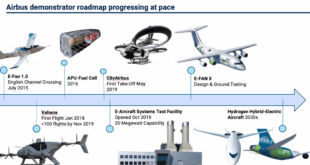
Companies team to develop hybrid propulsion
Aerospace giant Airbus, engine-maker Safran and aircraft manufacturer Daher have teamed up to develop the demonstrator using a wing-mounted distributed hybrid propulsion system. They plan for a maiden flight in 2022 using Daher’s TBM utility aircraft as a platform.
Distributed hybrid propulsion combines a gas turbine engine with an electrical generator and batteries powering multiple electric motors driving propellers. Airbus views the technology as an important step towards delivering the certification standards for a more electric aircraft, while Safran plans to become a market leader in the technology.
The companies are developing the plane as part of a three-way collaboration designed to validate technologies that reduce CO2 emissions, cut noise pollution and create new uses for air transportation. The project has the support of the French Civil Aviation Research Council (CORAC) as well as the nation’s civil aviation authority.
Safran will provide the distributed hybrid propulsion system, including a combined turbine and power generator, an electric power management system and the integrated “e-Propellers” to be built into the wings. The idea is that the e-propellers provide propulsion thrust while at the same time delivering aerodynamic gains by reducing wing surface and wingtip marginal vortices and drag.
Safran says it intends to be the market leader with this type of system by 2025. “Safran has developed a technology roadmap for the installation of electric thrusters on aircraft. EcoPulseTM offers us an excellent opportunity to evaluate and identify the specific features expected by this market, particularly in terms of new hybrid propulsion aircraft projects,’’ said Safran head of R&T and innovation Stephane Cueille.
Airbus will be responsible for the aerodynamic optimization of the distributed propulsion system and development of the control laws, while Daher will take care of component and systems installation, flight testing, overall analysis and regulatory construction. “Reducing the environmental impact of aircraft is a priority for the industry as a whole,’’ Daher aerospace and defense senior vice president Nicholas Orance said.
References and Resources also include:
https://www1.grc.nasa.gov/wp-content/uploads/2018EATS-Review-of-DEP-Hyun-D.-6.2018-4998.pdf