 International Defense Security & Technology Your trusted Source for News, Research and Analysis
Related Articles

Modeling and simulation (M&S) is the use of models as a basis for simulations to develop data utilized for managerial or technical decision making. Modeling is the process of representing a model (e.g., physical, mathematical, or logical representation of a system, entity, phenomenon, or process) which includes its construction and working. This model is similar to a real system, which helps the analyst predict the effect of changes to the system. Simulation of a system is the operation of a model in terms of time or space, which helps analyze the performance of an existing or a proposed system.
Success in the aerospace and defense industry demands that you deliver a high-uptime product with zero quality escapes. A fast, flexible approach to embedded software test is key for meeting tight deadlines and strict budgets. In many cases, the most effective way to develop an embedded system is to connect the embedded system to the real plant. When cost, availability, and safety make real-world testing of satellites and planes impractical, virtual testing reduces risk.
Hardware-In-the-Loop-simulation, or HIL, is a very powerful test methodology used for systematic testing of embedded software. Hardware-in-the-loop (HIL) simulation is a type of real-time simulation. The machine or physical part of the system called the plant is normally connected with the control system, through actuators and sensors. With HIL testing the plant is replaced by a simulation of the plant (called the HIL simulator). If the HIL simulator is designed well, it will accurately mimic the plant and can be used to test the control system. The embedded system to be tested interacts with this plant simulation. Carrying out a HIL Simulation to Test the Control System, Embedded System, etc. is called HIL Testing.
You use HIL simulation to test your controller design. HIL simulation shows how your controller responds in real-time to realistic virtual stimuli. You can also use HIL to determine if your physical system (plant) model is valid. This type of HIL simulation could be termed Controller-In-the-Loop (CIL) Simulation and has become a mainstay of the automotive, aerospace, marine, and defense industries.
The more traditional application of the HIL concept is controller design and testing, in which a control unit in hardware is integrated with virtual models of the devices and systems being controlled. Hardware-in-the-loop (HIL) simulation, or HWIL, is being used in the development and test of complex real-time embedded systems.
In HIL simulation, you use a real-time computer as a virtual representation of your plant model and a real version of your controller. The figure shows a typical HIL simulation setup. The desktop computer (development hardware) contains the real-time capable model of the controller and plant. The development hardware also contains an interface with which to control the virtual input to the plant. The controller hardware contains the controller software that is generated from the controller model. The real-time processor (target hardware) contains code for the physical system that is generated from the plant model.

A HIL simulation must include electrical emulation of sensors and actuators. These electrical emulations act as the interface between the plant simulation and the embedded system under test. The value of each electrically emulated sensor is controlled by the plant simulation and is read by the embedded system under test (feedback). Likewise, the embedded system under test implements its control algorithms by outputting actuator control signals. Changes in the control signals result in changes to variable values in the plant simulation.
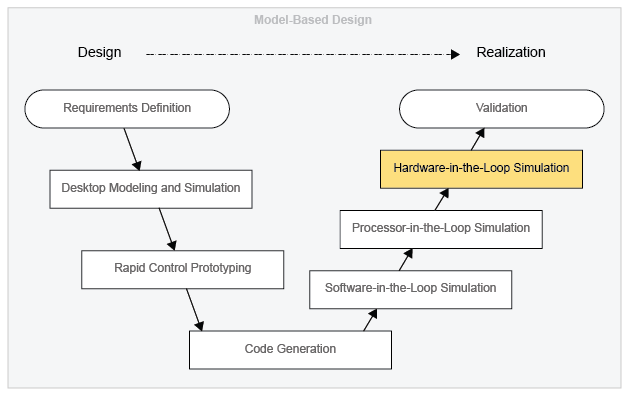
HIL simulation can be used to test the design of your controller when you are performing Model-Based Design (MBD). The figure shows where HIL simulation fits into the MBD design-to-realization workflow.
Hardware-in-the-loop (HIL) simulation is rapidly evolving from a control prototyping tool to a system modeling, simulation, and synthesis paradigm synergistically combining many advantages of both physical and virtual prototyping. Advances in both simulation and testing capabilities have opened the door for HIL simulation to metamorphose from a control validation tool to a system synthesis paradigm. In this case, major pieces of hardware performing physical tasks are integrated with virtual devices emulating realistic operating conditions based on predictions of a high-fidelity simulation. This paradigm shift is particularly important for modern automotive propulsion systems. The increasing complexity of such systems, coupled with the need to evaluate many options before finalizing a vehicle concept, motivates the application of the HIL system synthesis paradigm as an essential new tool for concurrent engineering.
This growing prevalence of HIL simulation attests to its many advantages, including:
1. Cost-effectiveness: HIL simulation often requires significantly less hardware than physical prototyping, thereby costing less.
2. Rapid prototyping: Because they often require less hardware than fully physical prototypes, HIL simulators can also be considerably quicker to build. Controller prototypes, for instance, can be built rapidly and evaluated in the loop utilizing the appropriate software platform.
3. Fidelity and verisimilitude: By prototyping in hardware those components whose dynamics or other attributes (e.g., transient emission formation in diesel engines) are not fully understood, HIL simulators often achieve fidelity levels unattainable through purely virtual simulation.
4. Simulation speed: HIL simulations of complex physical phenomena run faster than purely virtual simulations of the same phenomena (e.g. IC engine simulations based on Computational Fluid Dynamics).
5. Repeatability: Systems that normally operate in highly variable environments (e.g., off-road vehicle suspension systems) can often be tested in controlled lab settings through HIL simulation, which may significantly increase repeatability.
6. Non-destructive nature: HIL simulation often makes it possible to simulate destructive events (e.g., vehicle accidents, missile interception, etc.) without incurring costly destruction.
7. Comprehensiveness: HIL simulation often makes it possible to simulate a given system over a much broader range of operating conditions than what is feasible via purely physical prototyping.
8. Safety: HIL simulators can often be used to train human operators (e.g., airplane pilots) of safety-critical systems (e.g., supersonic aircraft) in significantly safer environments (e.g., flight simulators).
9. Concurrent systems engineering: Finally, HIL simulation allows different teams to develop different parts of a system in hardware without losing sight of integration issues, thereby enabling concurrent systems engineering.
Hardware-in-the-loop simulation testing for defense and aerospace systems
Cost and functionality factor into any design and development phase of a system: “HIL testing is invaluable because it allows these dangerous or difficult tests to be conducted with a great deal of fidelity, which saves cost and improves safety and reliability,” says Bill Eccles, principal electrical engineer at automated test, data acquisition, and control system manufacturer Bloomy in Hartford, Connecticut. “Though manufacturers always test their products in the real world, there’s simply no way they can exercise them in all conditions.”
The scalability and maturity of this technology has enabled aerospace and defense companies to use HIL simulation to test RF signals. “That’s pretty revolutionary that someone is using HIL with RF signals,” says Adam Foster, senior product manager for test systems at National Instruments in Austin, Texas. “HIL is a big thing for aerospace and defense. It allows them to go after more corner cases in complex situations.”
HIL subjects the part “to signals and conditions similar to those found in the real world. These signals are under the control of models of the real world, which run in a real-time test environment,” says Eccles. The part “then produces signals which feed back to these models, and that makes a complete loop. The result is that the flight control, system computer, engine control, or whatever ‘thinks’ it’s happily flying or rolling along even though it’s stuck on a rack in a lab somewhere.”
HIL simulation for radar systems have evolved from radar jamming. Digital Radio Frequency Memory (DRFM) systems are typically used to create false targets to confuse the radar in the battlefield, but these same systems can simulate a target in the laboratory. This configuration allows for the testing and evaluation of the radar system, reducing the need for flight trials (for airborne radar systems) and field tests (for search or tracking radars), and can give an early indication to the susceptibility of the radar to electronic warfare (EW) techniques.
HIL-simulation testing can be helpful when conducting coexistent-signal studies in radar applications. With the signal generator and spectrum analyzer, “one of the important elements for the hardware-in-the-loop studies for coexistence is the ability to do radar echo generation,” McCarthy states. Engineers can “set up a benchmark with the radar echo generator. You can put that at a runway at a fixed position, downrange of the radar, with ‘X’ number of signals at various amplitudes. Then as you introduce an interference signal, it could be cosite, it could be at an off-azimuth angle, it could be at a different amplitude or frequency,” McCarthy explains. At this point, he says, “you can start to test the immunity of the radar.”
The technology is also based on the same used in the wireless industry: “It is basically taking the communication technology used to create fading and multipath conditions to emulate cellphone propagation patterns.” The technology to create those multipath reflections is the same technology used to create echo returns in a radar, McCarthy notes.
With military radars, for example, “you can benchmark the radar and conduct a full functional performance validation of the radar by putting in different echo returns,” says Darren McCarthy, A&D technical marketing manager at Rohde & Schwarz USA in Beaverton, Oregon. “If your radar has the ability to receive a signal of -120 decibel-milliwatts (dBm) you can emulate ten targets offset in frequency, amplitude, and distance with ten returns.
“A couple dB each step and then you can test this sensitivity or selectivity of the radar as you introduced coexistent networks such as an LTE user device at a certain channel or frequency offset from that radar,” he continues. “By varying the frequency offset and amplitude, a complete evaluation of the radar’s performance and its susceptibility can be determined. By physically moving the coexistence signal to other angles of incidence, you can fully characterize the radar/antenna combination and come up with performance guidelines for the radar.”
Rohde & Schwarz has commercial off-the-shelf (COTS) vector signal generators and spectrum analyzers, such as the SMW200 and the FSW43, that “basically receive a signal, loop it back, and then allow users to control offsets and targets using Doppler, doing attenuation to emulate different radar cross-sections. Then as targets move away you can choose to have a typical link budget roll off of what the typical target would do.”
The SMW200 and the FSW43 can create radar echoes up to 40 GHz. Photo courtesy of Rohde & Schwarz.

Using HIL testing for aircraft
With airborne platforms, such as Saab Aerospace’s Gripen fighter aircraft, engineers used National Instruments’ HIL-simulation technology for integration testing of its LRUs. “Saab Aerospace is focusing on HIL simulation to help drive down cost. Aircraft simulations can be done using physics models and using signal processing. It’s not all software but it does require some hardware functionality in it,” Foster says. “There are certain safety factors; you want to ensure you have as much test coverage in as many of the corner cases that this vessel or instrumentation could be put in.”
Some simulations the aircraft can be placed in could be, for example, “If your airplane has engine failure, you need to be able to simulate how ECUs or LRUs are going to behave in these situations,” Foster continues. “HIL lets you simulate those things without having to do all of the physical tests for it. So you’re not going to have to build a prototype and staff it with somebody flying it and force them to do a nose-dive or blow up one of the engines.”
Essentially, “HIL tricks the LRU, or ECU, or onboard control unit into thinking it’s actually flying, and so it requires a lot of sophisticated instrumentation both to send the stimulus signal as it would be recorded or determined from physics models or recorded from empirical data,” he says.
Testing the aircraft requires the engineer to understand every minute detail of the aircraft, from what type of material the wing is made of, to how fast the airplane will go, to what the wind conditions look like with humidity, Foster explains. “All that simulation and information requires an immense amount of processing power, but what you do is you basically plug in the ECU and run it through various permutations of flying conditions and failure modes, all while you’re logging data.”
As software becomes more prevalent, the “microtrend of hardware-in-the-loop would be as we digitize everything, and as we switch from mechanical control to electronic control, you get the ability to test it and continue to squeeze cost out of it. All the while you are creating physics models and running simulations that would give you very reliable results between simulated and real,” he adds.
HIL Simulator technology
Numerous key enablers must come together seamlessly to furnish a synergistic HIL simulation setup. HIL simulator is in essence a control system whose virtual components command its hardware to “track” a hypothetical reference “system.” The virtual models within a HIL simulator must typically meet two important requirements. First, they must capture the dynamics of the virtually prototyped systems accurately enough to enable the HIL simulator to achieve its required simulation and design goals. Secondly, they must run in real time: a
requirement that often translates into a bound on model complexity. These two requirements, fidelity and simplicity, typically conflict. This can provide superb concurrent systems engineering capabilities to designers. For these reasons, researchers have recently begun to examine the distribution of a HIL simulator’s components over a network.
The ability of a HIL simulator to capture the behavior of a system rests on the fidelity, bandwidth, and unobtrusiveness of the simulator’s sensors and actuators. A HIL setup’s sensor measurements must often undergo significant processing before they can be fed into the setup’s virtual simulation. Typical processing tasks include digital signal decoding, anti-alias filtering (for analog signals), noise attenuation, etc. Such signal conditioning tasks are often performed separately by a digital signal processor within a HIL interface board to free the main HIL microprocessor for virtual simulation.
Since the interactions between the physical and virtual components of a HIL simulator are bidirectional, it is crucial that the time frames of
these components match exactly. This implies that the virtual components must run in real time, which places tight requirements on the HIL simulator’s microprocessor, operator system, and integration routine. Specifically, fast microprocessors and – in some cases, even faster field-programmable gate arrays (FPGAs) –are often used by HIL simulators to enable real-time virtual simulation. Furthermore, even with such fast processors, running a HIL simulator in real time necessitates a special kind of operating system that executes integration steps at regular intervals signaled by clock interrupts. Such real-time operating systems are a mainstay of HIL simulation, and Liu17 provides a thorough review of their different types (e.g., “soft” vs. “hard”) and architectures.
The possibility of distributing a HIL simulator’s physical and virtual components over a network can be quite attractive for three reasons. First, the different pieces of hardware needed for a particular HIL simulation may not be physically collocated or mobile. Secondly, distributing the virtual components of a HIL simulator can provide increased virtual simulation capabilities compared to the use of a
single processor. Finally, the ability to network the various components of a HIL simulator makes it possible to build different HIL simulators of different components of a system independently and then combine them into a larger, system-level HIL simulator. This can provide superb concurrent systems engineering capabilities to designers. For these reasons, researchers have recently begun to examine the distribution of a HIL simulator’s components over a network.
https://www.youtube.com/watch?v=iouY7iYJoeA
References and Resources also include: