 International Defense Security & Technology Your trusted Source for News, Research and Analysis
Related Articles

Transmission Line principles
Transmission lines are means of transporting RF energy between subsystems. A simple wire lead does not work well for RF and microwave applications due to its large dimensions relative to a wavelength and losses due to the skin effect. To take into account the unique characteristics of high-frequency transmission lines, a more appropriate definition is “a device used to transfer energy from one point to another efficiently.” An efficient transfer of energy is one with a minimum amount of reflective loss (i.e. close to a perfect match, or VSWR = 1:1), as well as the minimum amount of resistive loss due to mechanisms such as the skin effect. This is important at RF and microwave frequencies because as frequency increases, energy lost in a transmission line is more difficult and costly to recover.
There are many examples, the most common transmission line that you all know about is the coaxial cable. A parallel transmission line with two parallel wires is also called twin leads. More modern versions of transmission lines are all embedded in planar technologies like PCB technology or semiconductor technology. Examples of such transmission lines include microstrip lines, strip lines which have two ground lines and in-between strip and coplanar waveguide
transmission lines, which in principle do not require per se a ground plane at the bottom, and they are often used in semiconductor technologies. Another type of transmission line is a waveguide, either rectangular or circular.
An equivalent circuit for a section of the transmission line is shown in Figure. There are four parameters to consider: inductance (L), resistance (R), capacitance (C), and conductance (G). There is also the dielectric constant, ε, of the insulating material in the transmission line. Values for each of the four parameters are expressed in their appropriate units per unit length.
The inductance (microhenries/unit length) in a transmission line is due the current flowing in the metallic conductor. Alternating current (AC) flowing through the conductor produces a magnetic field. The arrangement of fields sets up an inductance on the transmission line that can be characterized as an inductance per unit length. Inductive reactance, which is the Ohmic result of inductance, increases with frequency and can cause problems for high frequency circuits.
The resistance (Ohms/unit length) shown in Figure is also associated with the metallic conductor and current flow. Any time current flows through a metallic conductor, there is a loss due to finite resistance in the conductor. This obeys Ohm’s law, which requires a voltage drop across a resistance when current flows through it; thus, the loss in the conductor of a transmission line is caused by current flowing through its resistance causing a voltage drop. The total loss of power in a transmission line is often specified in decibels per metre (dB/m), and usually depends on the frequency of the signal.
The last two parameters are associated with the dielectric used in the transmission line. The first parameter is capacitance (farads/unit length). A capacitor has two conductive plates of a certain area separated by distance with a dielectric between them. One plate is the center conductor and the other is the ground, or shield. These plates have an associated area per unit length separated by the dielectric in between, creating a capacitance per unit length. Capacitive reactance, which is a result of the line capacitance, decreases with an increase in frequency and causes the propagating signals to be shorted to ground at certain frequencies. So, the distributed capacitance, as well as the distributed inductance and resistance of transmission lines should, in general, be minimized.
Conductance (siemens/unit length) is the amount of leakage through the dielectric. There is always a certain amount of conductance, because there is no such thing as a perfect dielectric. That means a certain amount of energy passing down the transmission line appears at the other conductor. It usually is a very small quantity, because many dielectrics are very good insulators in transmission line applications. Conductance is represented by a shunt resistor between the signal wire and the return wire (ground).
The term dielectric constant (ε) is the electrical property of the dielectric material that is between the conductors in a capacitor or transmission line. This may be air, Teflon or other material. It is a relative value equal to the ratio of the electric field in a vacuum divided by the electric field in the medium. The insertion of a dielectric medium between capacitor plates increases its capacitance or ability to store opposite charges on each plate. The dielectric constant of air is considered to be 1.

In particular, the voltage can be represented by an exponential function which represents a wave propagating in the plus direction, which is the first term in this equation with an amplitude V nought plus. We also have a wave propagating in the minus Z direction with a voltage amplitude
V nought minus, and the same holds for the associated current waves.


Now, gamma, which is the complex propagation constant, has two components. A real part alpha, that’s the attenuation along the line M beta, which is the phase constant, which is related to the phase velocity of the wave propagating along the line. Gamma can also be expressed in terms of the equivalent circuit components: R, L, G, and C.

Another important parameter is the characteristic impedance of the transmission line.


We short-circuit the end of the transmission line, in that case, Z_L is zero and we see that the reflection coefficient is equal to minus one. In terms of an open then Z_ L is infinite and the reflection coefficient is one. In both cases, short and open, all the energy is reflected back in the line. If we terminated the transmission line with the load, which means that the termination impedance is exactly the same as the characteristic impedance. We see that the reflection
coefficient is zero, and that’s often of course what we would like to see.
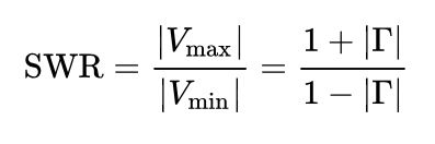
The relation between the maximum and the minimum is called the voltage standing wave ratio. This is a very important measure, for example, for power amplifiers, because if you would
connect a power amplifier, for example, tuned antenna and the VSWR would be very high. Then the maximum voltage along the output of the power amplifier could be higher even than the
breakdown voltage. Now the terminated lossless line has also the property that if the reflection is not zero, that the voltage along the line will fluctuate.
The input impedance: The characteristic impedance of a transmission line is the ratio of the amplitude of a single voltage wave to its current wave. Since most transmission lines also have a reflected wave, the characteristic impedance is generally not the impedance that is measured on the line. The impedance measured at a given distance l from the load impedance may be expressed as


The input impedance of a lossless transmission line: For a lossless transmission line, the propagation constant is purely imaginary. We can write the input impedance in terms of the load impedance, the characteristic impedance and a term tangent beta L.

So beta is 2pi over lambda, and L is the length of the line. Now, this is a very important equation because we can see that by varying the line length, we can change the input impedance. So we can change it to all kinds of values, which is a very important feature. So this is in fact, an impedance tuner.

Short: For the case of a shorted load, the input impedance is purely imaginary and a periodic function of position and wavelength (frequency)

Now, in the particular case that we choose l to be lambda over eight, so the wavelength is divided by eight. We find that tangent beta l, in that case, is equal to one, which means that we have a kind of the equivalent of a lumped element. In this case, an inductor, because an inductor, the impedance is j omega L
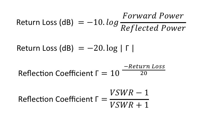
Now, an important parameter of such terminated transmission line is the return loss. And the return loss, which is often used to specify certain termination, is now defined as in log arithmetric scale in dBs, in decibels and can be found by taking the log of gamma times 20.
Coaxial cables
Coaxial cables are the form of an electrical cable that includes an inner conductor covered by a concentric conducting shield, that are separated by a dielectric. In simple words it is a system that comprises the inner conductor and outer shield sharing a geometric axis separated by an insulating material to transmit electricity. It can carry high-frequency electrical signals with low losses. Its design is based on physical size, frequency performance, attenuation, power handling capabilities, flexibility, strength, and cost. It is most commonly used in telephone trunk lines, broadband internet networking cables, high-speed computer databases, cable TV connections, etc.
Different types of coaxial cables
The standard flexible coaxial cable is composed of the outer plastic sheath, woven copper shield, inner dielectric insulator, and copper core.
1. Hard-line coaxial cable – It is made up of round copper, silver, or gold tubing or a combination of such metals as a shield. The center conductor is generally made up of solid copper or copper-plated aluminum. Dielectric is usually in the form of polyethylene foam, air or pressurized gas as nitrogen, etc. They usually have a larger diameter. The gas-filled hard-lines are mainly used for TV or radio broadcasting, military transmitters, amateur radio applications.
Semi-rigid coaxial cable – It consists of a metal tube made up of copper outer sheath. They are stand-alone microwave components. They have a wide frequency range up to 65 GHz. They can form a shape and retain it for a longer time. They are phase stable. Also, this cable has low passive inter-modulation. It is the most preferred cable type for its broad frequency capabilities, reliable electrical performance, and phase stability.
Rigid coaxial cable – It is made up of two copper tubes placed in concentric patterns every other meter using supports. It cannot be bent so often it needs an elbow. They are connected with the help of connectors. They are commonly used indoors for interconnection between high power transmission and other RF components. Sometimes it comes with specialized braces and springs. These springs help in differential expansion and contraction of inner and outer copper lubes used in the transmission line run.
Twin axial cable – It comes with 2 inner conductors instead of one. It is suitable for very short-range high-speed differential signaling applications. It has a reduced cable loss, higher protection from ground loops and captive fields, and lower low-frequency magnetic noise. They are commonly used for low frequency digital and video applications, high-performance computing clusters, data center networks and storage, server applications.
High-temperature coaxial cable H- They are used in a wide variety of configurations to suit every harsh environment application. The temperature range for the majority of the coaxial cable is -55/+200 degree and for triaxial cable -55/+150 degree.
Military Cable market
The main types of military cables are coaxial, ribbon, and twisted pair. The coaxial cables are used for various military applications such as communications, aircraft and in-flight entertainment. The coaxial cable refers to an electrical cable that has a copper conductor, an insulator shielding, and a braided metal mesh to prevent signal interference and cross-talk. Coaxial cable is also referred to as coax.
The core copper conductor is utilized for signal transmission, while the insulator provides insulation to the copper conductor. The various types of materials used in the military cables include stainless steel alloys, aluminum alloys, copper alloys, and other materials such as nickel and silver. The military cables are mainly produced for platforms such as ground, airborne, and marine that are used in applications such as communication systems, navigation systems, military ground equipment, weapon systems, and others such as displays and accessories.
The global military cable market is expected to grow from $21.68 billion in 2021 to $23.55 billion in 2022 at a compound annual growth rate (CAGR) of 8.6%. The global military cable market is expected to grow from $23.55 billion in 2022 to $256.99 billion in 2026 at a compound annual growth rate (CAGR) of 81.8%. The increase in military spending will propel the growth of the military cable market.
Military cable assemblies and wire harnesses are those that have been designed, built, and manufactured to MIL-SPEC specifications. All types of cables and lines installed in the military sector must meet chemical, thermal and mechanical requirements according to the highest standards.
Military cable assemblies and wire harnesses must be built with military-specified and/or approved wire, cable, connectors, terminations, and other components. Military spending can be viewed as a function of driving forces within the context of current economic and political restrictions. Military expenditure is determined by four basic factors: security-related, technological, economic and industrial, and, more broadly, political.
Segments
1) By Product: Coaxial; Ribbon; Twisted Pair
2) By Conductor Material: Stainless Steel Alloys; Aluminum Alloys; Copper Alloys; Others
3) By Platform: Ground; Airborne; Marine
4) By Application: Communication Systems; Navigation Systems; Military Ground Equipment; Weapon Systems; Others
Key Vendors
Some key military cables market players are Carlisle Interconnect Technologies, Collins Aerospace, Prysmian Group, Nexans S.A, Sumitomo Electric Industries Ltd, A E Petsche, Axon Cable.
In January 2021, Carlisle Interconnect Technologies, a US-based company that manufactures high-performance wire and cable, including optical fiber has unveiled its new UTiPHASE microwave cable assembly line, a revolutionary technology that provides exceptional electrical phase stability versus temperature without sacrificing microwave performance.
UTiPHASE is appropriate for high-performance defense, space, and testing applications. The UTiPHASE series expands on CarlisleIT’s acclaimed UTiFLEXR flexible coaxial microwave cable technology by combining renowned dependability and industry-leading connection captivation with a thermally phase-stable dielectric that eliminates the PTFE knee. This scenario is efficiently mitigated by UTiPHASE’s™ thermally phase-stable dielectric, which flattens the phase vs. temperature response curve, lowering system phase variance and boosting accuracy.
References and Resources also include:
https://www.microwavejournal.com/articles/30170-transmission-lines