 International Defense Security & Technology Your trusted Source for News, Research and Analysis
As technology advances and demand for faster, more reliable communication systems grows, millimeter-wave (mmWave) frequencies are becoming increasingly essential in various industries. Millimeter-wave (mmWave) technologies are revolutionizing several sectors, including 5G cellular communications, Ka-band satellite communications, and military and automotive radar systems. These high-frequency bands, typically ranging from 30 GHz to 300 GHz, enable faster data transfer, higher resolution sensing, and more efficient communication systems.
These high-frequency signals enable ultra-fast data rates, superior coverage, and enhanced connectivity, but they also pose significant challenges in testing and measurement due to their unique propagation characteristics and susceptibility to signal degradation. Issues such as propagation loss, signal integrity, and the complexity of accurate measurements demand advanced testing solutions.
As these technologies evolve, precise and reliable testing becomes indispensable to ensure optimal performance. This requires sophisticated tools and techniques to accurately characterize and evaluate mmWave systems across various applications, including communication, radar, and satellite systems, in these rapidly advancing fields.
Understanding Millimeter waves and their applications
Millimeter waves are electromagnetic signals with frequencies ranging from 30 to 300 GHz that correspond to wavelengths of 10 to 1 mm in the free space. Electromagnetic waves in the millimeter-wave band (with frequencies between 30 and 300 GHz, or wavelengths between 10 and 1.0 mm) have attractive characteristics. One of their features is the wider usable frequency band compared with waves in the microwave band or lower bands. Another feature of using the millimeter-wave band is the fact that it becomes possible to design smaller and lighter equipment that utilizes that band. So it is useful to adapt millimeter waves for short-range broadband communication systems, high resolution sensing systems and radio astronomy.
Such signals in natural atmosphere environment are susceptible to attenuation at different rates for different wavelengths (frequencies) which makes them very useful in specific applications. Frequencies where the average absorption of mm-waves is the lowest are called low attenuation windows and occur mainly around 35, 77 and 94, 140, 220, 340, 410, 650 and 850 GHz. The regions with highest averaged absorption levels are called attenuation lines and can be seen around 22, 60, 118, 183, 320, 380, 450, 560, 750 GHz.
The atmospheric attenuation of mm-waves is caused by gases and constituents that naturally occur in the environment. It is the oxygen molecules that are responsible for high attenuation at 60, 118 and 560 and 750 GHz. The rest of the attenuation lines are caused mainly by water droplets of various diameter sizes as well as other chemical species (CO2, N2O, NO, SO2 and SH2) at submillimeter wavelengths. Due to different properties of mm-waves at different frequencies and environmental conditions the applications of mm-waves vary largely from communications, imaging and security applications, radar, radiometry and atmospheric sensing.
MM Wave Applications
The mm-wave applications correlate closely with how such signals propagate in the atmosphere. The frequencies for which atmospheric attenuation is low (44, 86, 94, 140 GHz) are particularly useful in communication system operating at long ranges such as: satellite communications, backhaul mm-wave radios and point to multi-point radio links. For short range communications the 60 GHz band provides enough range where only a local area, short distance transmission is required. Other application benefiting from low atmospheric attenuation would include automotive radars at 24, 77 and 94 GHz where a long range transmission and reception is possible.
Imaging and security utilizes a mixture of high and low attenuations bands for passive and active systems. These use 77, 94 and 183 GHz frequencies as these signals present good properties to penetrate many materials (i.e. clothing) and see through the fog and rain. For those materials that can not be penetrated the atmospheric environment provides a good thermal contrast from which images can be synthesized at post processing level.
A cornerstone in the ability to achieve self-driving vehicles is the ability to detect and avoid obstacles. Millimeter wave radar technology is advancing rapidly to support the array of sensors needed. Automotive Radar Frequency Bands are 24, 77, and 79 GHz. Consumer WiFi applications have expanded beyond what is available from 802.11ac devices. The designation 802.11ad is an extension of the IEEE’s popular 802.11 family of wireless local-area network (LAN) standards. The 58 to 64 GHz spectrum has long been available for unlicensed services, and was recently expanded up to 71 GHz (FCC Part 15). Examples of applications are high-speed wireless multimedia services, including uncompressed high-definition TV (HDTV) and instantaneous music and image data transmissions.
5G Cellular Communications: Unlocking Ultra-Fast Wireless Networks
5G technology promises to revolutionize mobile communications with faster speeds, reduced latency, and increased connectivity. Unlike its predecessors, which operate at lower frequencies (below 6 GHz), 5G utilizes a broad range of mmWave frequencies to meet the growing demands for data traffic and network capacity. Operating in the 24 GHz to 100 GHz range (specifically the 28 GHz, 39 GHz, and higher bands), mmWave frequencies enable significantly higher bandwidth, making it possible to achieve gigabit speeds that are essential for applications like virtual reality, augmented reality, and autonomous vehicles.

These frequencies allow for higher bandwidths, which are essential to meet the demanding requirements of enhanced mobile broadband (eMBB) applications, such as virtual reality (VR), augmented reality (AR), and ultra-high-definition video streaming. 5G New Radio (NR) demands significantly faster data rates to support enhanced mobile broadband (eMBB) use cases such as ultra-high-definition (UHD) video streaming, virtual reality (VR), and augmented reality (AR).
The eMBB use case targets data rates of up to 20 Gbps in the downlink (DL) and 10 Gbps in the uplink (UL), leveraging higher-frequency millimeter-wave (mmWave) bands alongside sub-6 GHz frequencies. The 5G networks will operate across a broad spectrum range, with key mmWave bands like 28 GHz and 39 GHz playing a pivotal role due to their abundant spectrum availability and ability to support aggregated channel bandwidths of 1 GHz or more. While LTE remains integral to 5G, the prominence of mmWave frequencies is expected to grow, enabling unparalleled performance and connectivity for next-generation applications.
However, testing mmWave 5G systems involves numerous challenges, including signal propagation, antenna alignment, and interference from environmental factors such as rain, foliage, and buildings.
At mmWave frequencies, path loss becomes a significant challenge. RF power diminishes rapidly over short distances, making signal propagation less reliable compared to lower-frequency bands like those used in 4G LTE. The shorter wavelengths at higher frequencies lead to increased attenuation due to obstacles like buildings, trees, and even human bodies. This necessitates the need for more sophisticated test solutions to ensure reliable communication and accurate measurements for 5G devices.
As a result, testing for 5G mmWave devices requires precise measurements of signal quality, including parameters such as gain, directivity, beamwidth, and antenna efficiency. Rigorous testing is required to ensure optimal performance, including accurate measurements of signal strength, beamforming, interference, and channel modeling.
The design of devices for mmWave frequencies presents additional complexities. The smaller size of 5G devices, along with the growing number of antennas integrated into each device, complicates testing. While 4G LTE smartphones typically feature several antennas, 5G devices may have many more, often without the connectors needed for traditional testing setups.
This is further compounded by the fact that many 5G components are highly integrated and do not provide easy access for probing. Additionally, due to the compact size and integration of 5G devices, traditional testing setups with connectors are becoming increasingly difficult. As a result, over-the-air (OTA) testing methods have become a critical aspect of validating the radio performance of mmWave devices.
Many 5G components are designed as system-in-package (SiP) solutions, which require over-the-air (OTA) testing to accurately measure performance. For 5G testing, far-field radio characterization is essential. This includes assessing the antenna’s 3D radiation pattern, beamforming capabilities, and overall efficiency across multiple mmWave frequencies.
The most common 5G mmWave bands, like 28 GHz and 39 GHz, are already in use, with future deployments potentially extending up to 67 GHz. To keep pace with these advances, test solutions must be adaptable and capable of measuring higher frequencies as they become available. Furthermore, with the emergence of system-in-package (SiP) solutions, testing will need to occur both at the component level and the system level, requiring more flexible testing platforms.
To address these challenges, test solutions must evolve to provide efficient, repeatable, and flexible methodologies. This includes the integration of advanced packaging technologies and adaptable test systems that can support a variety of mmWave bands and configurations, ensuring that engineers can conduct thorough and effective validation across the full range of 5G devices and networks.
Test systems must be capable of characterizing a broad range of frequencies and configurations, ensuring that devices can perform reliably in real-world conditions. For effective testing, advanced mmWave test equipment, such as vector network analyzers (VNAs) and spectrum analyzers, are employed to characterize the behavior of 5G devices and networks. Additionally, real-world testing in urban and rural environments is critical to validate system performance in various deployment scenarios.
In conclusion, while mmWave frequencies hold great potential for 5G and beyond, they also present significant challenges in terms of signal propagation, antenna design, testing methodology, and instrumentation. Overcoming these challenges requires advanced testing solutions, innovative measurement techniques, and a deeper understanding of mmWave characteristics.
Ka-Band Satellite Communications: High-Speed Data Transmission for Global Connectivity
The Ka-band, which covers the frequency range of 26.5 GHz to 40 GHz, has become a key band for satellite communications, especially for high-throughput systems that require large amounts of bandwidth. Ka-band satellites offer faster, more reliable communication for internet services, broadcasting, and military applications, thanks to their ability to provide high-speed data transmission over large distances.
Testing Ka-band satellite communication systems presents its own set of challenges, particularly due to the need for high-precision measurements of transmitted and received signals. The higher frequencies used in Ka-band systems are more susceptible to atmospheric absorption, rain fade, and other environmental factors.
Atmospheric attenuation in the Ka-band is significant due to the interaction of mmWave signals with water vapor and other atmospheric components. Therefore, precise testing methods are needed to evaluate signal strength, link performance, and data throughput in various weather conditions.
Accurate testing requires systems capable of simulating the space environment, including signal degradation and path loss, to ensure robust communication links. This includes testing satellite terminals, ground stations, and antennas to verify their performance in various conditions, including rain fade, which is particularly important for satellite systems operating in the Ka-band.
Advanced equipment such as high-frequency signal generators, power meters, and spectrum analyzers are used to measure parameters like signal-to-noise ratio (SNR), error rates, and bit error rates (BER) to ensure robust communication links. Moreover, for satellite system deployment, rigorous field testing is conducted to measure performance in different geographic locations and across various satellite transponders to ensure optimal coverage and reliability.
Military Radar: Enhancing Detection and Surveillance Capabilities
Military radar systems operate in a wide range of frequencies, including the mmWave spectrum, to enable precise detection, tracking, and surveillance of objects. Radar systems operating in mmWave frequencies are increasingly used for advanced military applications, such as air defense, missile guidance, and battlefield surveillance. These systems offer advantages such as higher resolution imaging, improved accuracy, and better target discrimination, which are crucial for modern defense strategies.
Testing mmWave radar systems for military applications requires specialized equipment and techniques to measure key parameters such as signal strength, range, resolution, and radar cross-section (RCS). Furthermore, radar systems at mmWave frequencies require precise measurements of antenna directivity, beamwidth, and efficiency to ensure the radar system can accurately track and target objects.
Advanced radar test systems, including radar test chambers and range simulators, are employed to simulate real-world environments and test the radar’s ability to detect and track targets under various conditions. Calibration of radar equipment is also essential to ensure accuracy, as small errors can have significant consequences in military applications.
Additionally, electromagnetic compatibility (EMC) and interference testing are critical to ensure that radar systems do not cause or suffer from unwanted interference, especially in crowded electromagnetic environments.
Automotive Radar: Enabling Safe and Autonomous Vehicles
Automotive radar systems, which operate in the mmWave range (typically around 77 GHz), are essential components in modern vehicles, enabling advanced driver-assistance systems (ADAS) such as adaptive cruise control, collision avoidance, and parking sensors. The high resolution of mmWave radar enables vehicles to detect objects with great precision, even in challenging conditions like low visibility, fog, or rain. With the rise of autonomous vehicles, mmWave radar plays an even more critical role in providing accurate, real-time data for object detection, navigation, and safety functions.
Testing automotive radar systems requires precise measurements of radar range, resolution, and object detection capabilities under various driving conditions. The key challenges lie in ensuring the radar can operate effectively in diverse environments and handle complex scenarios involving multiple objects and dynamic conditions. The mmWave radar systems must be tested for their ability to detect and track objects in dynamic environments, including high-speed motion, adverse weather conditions, and complex traffic scenarios.
Testing automotive radar systems requires specialized equipment to measure radar performance, including RCS, SNR, and range accuracy. Test systems must be able to simulate real-world environments, such as varying weather conditions, to ensure automotive radar systems function reliably in all situations. For this purpose, specialized testing tools such as radar test benches, anechoic chambers, and dynamic test vehicles equipped with radar sensors are used.
These systems allow engineers to simulate real-world driving conditions and evaluate the radar’s performance in detecting objects at various distances, speeds, and angles. Additionally, calibration of radar sensors is critical to ensure accurate measurement of distances and speeds for safe autonomous navigation.
Key Challenges in mmWave Testing
Regardless of the application, mmWave testing faces several common challenges. First, the short wavelength of mmWave signals makes them highly susceptible to path loss and atmospheric attenuation, which complicates signal measurement and analysis. To address this, engineers use sophisticated test solutions, including OTA testing, far-field characterization, and specialized measurement tools designed to minimize path loss and optimize signal-to-noise ratio (SNR).
The high-frequency nature of mmWave signals also requires precise measurements of antenna characteristics, such as gain, directivity, and beamforming performance. These measurements must be conducted across a wide range of frequencies to account for the diverse operating conditions and deployment scenarios in 5G, satellite, military, and automotive systems.
Another key challenge in mmWave testing is the integration of components into compact, system-in-package designs. These designs often lack traditional connectors, making it difficult to access specific points for probing. As a result, test systems must be flexible enough to accommodate both component-level and system-level testing, particularly for highly integrated mmWave devices.
Diverse Frequency Bands and Far-Field Testing
One of the most significant challenges in 5G mmWave testing is the diverse range of radio frequencies being used.
Short-range communications leverage the 60 GHz band for local area transmissions, while automotive radars (24, 77, and 94 GHz) utilize low-attenuation frequencies for long-range obstacle detection. Imaging and security applications use both high- and low-attenuation bands (77, 94, and 183 GHz) for systems capable of penetrating materials like clothing or generating thermal contrast-based images in adverse weather. Additionally, mmWave technology underpins advancements in self-driving vehicles and has enabled high-speed consumer Wi-Fi (802.11ad) in the 58–71 GHz spectrum, supporting applications such as uncompressed HDTV and instant multimedia transmissions
While the 28 GHz and 39 GHz bands are currently the most common, future 5G networks could employ mmWave frequencies ranging from 26.5 GHz to 67 GHz. This wide range of operating frequencies demands testing systems capable of providing comprehensive radio characterization across these bands. Parameters such as gain, directivity, beamwidth, 3D radiation patterns, and antenna efficiency need to be measured accurately across these varying frequencies.
Given the compact and integrated nature of 5G components, engineers require flexible test platforms that can be easily adapted to test various mmWave bands and network configurations. A modular test system, capable of incorporating different hardware and software components, can be used to prototype multiple mmWave frequencies with the same baseband hardware.
Path Loss and Propagation Challenges
These frequencies have shorter wavelengths, which lead to increased signal attenuation and reduced range compared to lower-frequency signals. These signals are also prone to attenuation due to atmospheric factors like rain, foliage, and buildings.
Signal-to-Noise Ratio (SNR) and Measurement Challenges
Another key challenge at mmWave frequencies is the lower signal-to-noise ratio (SNR). The excessive path loss at mmWave frequencies results in weaker signals, which can make it difficult to perform accurate measurements for transmitter parameters like error vector magnitude (EVM), adjacent channel power (ACP), and spurious emissions. To mitigate this issue, engineers often reduce signal analyzer attenuation to improve the SNR, but even with attenuation set to 0 dB, SNR can still be insufficient for reliable signal analysis.
Minimizing path loss is crucial in mmWave testing to ensure that measurements remain accurate and reliable. This can be achieved by optimizing test setups, reducing cable losses, and using advanced instrumentation designed specifically for mmWave testing.
Over-the-Air (OTA) Testing
The compact and highly integrated design of mmWave devices also presents challenges. Measuring key RF parameters such as signal gain, directivity, beamwidth, and antenna efficiency is particularly challenging due to the smaller device and array sizes in 5G systems. Even minor alignment issues in connections can lead to unwanted reflections, degrading signal quality.
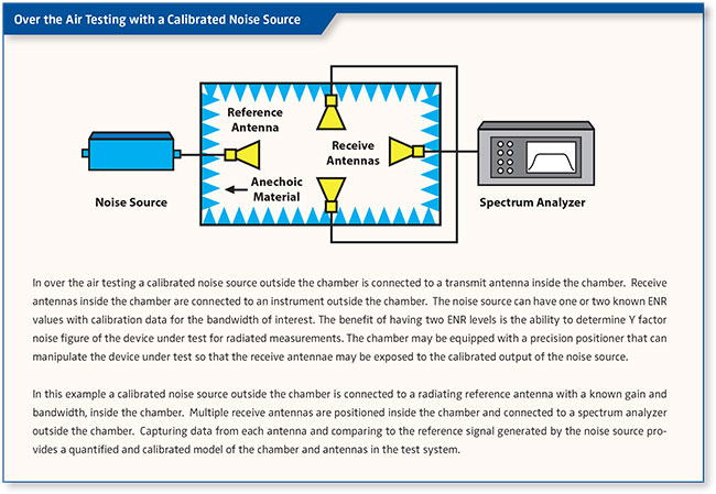
Many components, including transceivers integrated with antennas and RF front-end modules (FEMs) in system-in-package designs, lack probing points, meaning that traditional conducted testing methods become impossible. Instead, engineers must rely on radiated tests or over-the-air (OTA) testing to evaluate the performance of the devices in real-world conditions. OTA tests are used to simulate real-world environmental conditions, including interference and propagation effects, to validate a device’s performance in a network. For instance, 5G transceivers, which often need to be tested in conjunction with their antennas, are typically tested in OTA setups to account for complex interactions between the device and the environment.
Antenna Design and Testing Challenges
The mmWave spectrum requires precise RF parametric measurements for key attributes such as signal gain, directivity, beamwidth, and antenna efficiency. These measurements are further complicated by the smaller sizes of 5G devices and the advanced phase array antennas used in these devices. Even slight misalignments in flange connections can introduce unwanted reflections, degrading the overall signal quality and power.
The antenna is a critical area of focus when it comes to mmWave frequencies. The increasing use of phase array antennas, which rely on precise beam steering for optimal signal transmission, introduces additional testing challenges. To achieve the desired signal quality, 5G devices require greater accuracy in antenna gain measurements. However, testing these antennas in mobile devices can be tricky due to the high number of antennas required by 5G networks. Unlike 4G LTE devices, which have only a few antennas, 5G smartphones and terminals may include dozens of antennas. With the shrinking size of devices, providing a separate measurement connector for each antenna can be impractical.
As field trials for 5G mmWave radios have already shown, the measurement of signal profiles, range, and capacity for higher-gain antennas is far more complex than traditional LTE testing. The increased use of system-in-package (SiP) designs, where antennas are integrated with the RF front-end module (FEM) and transceivers, further complicates testing by eliminating external probing points.
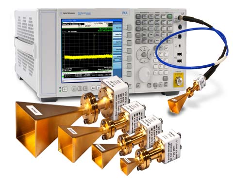
To meet the challenges of mmWave testing, engineers require specialized instrumentation designed to operate at these higher frequencies. Traditional microwave test equipment, typically designed to operate below 20 GHz, is insufficient for testing 5G devices at mmWave frequencies. Instead, frequency extension sources (FES) are used to extend the range of these instruments, allowing them to cover the broader mmWave spectrum.
Signal generators, analyzers, network analyzers, and power meters are some of the key test equipment used in mmWave testing. These instruments must be able to provide accurate and repeatable measurements across a wide range of frequencies. Frequency multiplication or mixing techniques are often used to extend the range of these instruments, allowing them to operate at mmWave frequencies above 110 GHz.
Millimeter Wave Instrumentation
Traditional test and measurement instruments, typically designed to operate below 20 GHz, have long sufficed for evaluating and testing most communication and radar systems. However, with the rapid emergence of millimeter-wave (mmWave) applications, there is a growing demand for measurement systems capable of functioning at frequencies above 20 GHz and, increasingly, beyond 110 GHz. These advanced systems achieve higher frequency ranges by utilizing frequency multiplication or mixing techniques, effectively extending the capabilities of standard instruments to address the unique challenges posed by mmWave technologies.
The selection of measurement systems is driven by the specific requirements of the mmWave application and its associated specifications. Engineers commonly rely on four key groups of test and measurement equipment for component and system evaluation: signal generators, signal analyzers, network analyzers, and power meters, each available in scalar or vector configurations. In addition to these, specialized tools such as noise figure analyzers and phase noise measurement systems are often necessary for applications demanding precise evaluation of signal integrity, noise performance, and phase stability. These advanced instruments enable accurate characterization and validation of mmWave devices, supporting the development of cutting-edge technologies across industries.
Signal Generators for Millimeter Wave Applications
Modern test laboratories demand high-stability signal sources for use as local oscillators in mixer applications or as RF sources in antenna and receiver testing. For millimeter-wave (mmWave) applications, signal sources must also cater to unique requirements, such as on-wafer device testing. These applications benefit from compact, repeatable extension sources that can be mounted directly on wafer probing station positioners near the device under test (DUT). Placing signal sources closer to the DUT reduces losses associated with long cables at high frequencies, improving overall measurement accuracy.
Signal generation at mmWave frequencies introduces new challenges, as errors like phase noise, IQ imbalance, and frequency response distortions become more pronounced. These factors need careful consideration to fully exploit the potential of wideband mmWave technology. Generating high-quality signals with low error vector magnitude (EVM) and minimal spurious content is crucial to ensuring that the system under test performs as intended. Such precision is particularly important for evaluating advanced technologies in 5G, automotive radar, and satellite communications.
Error Vector Magnitude (EVM) is a critical metric for evaluating the performance of communication systems, particularly in mmWave testing. EVM measures the deviation between the ideal transmitted signal and the actual signal received. A lower EVM indicates better signal quality, which is essential for ensuring accurate data transmission and system reliability.
Signal generators used in mmWave testing must provide high stability and low EVM to simulate real-world conditions accurately. High stability ensures consistent output signals, while low EVM minimizes distortion and errors in the generated signals. This allows for precise evaluation of the system under test, helping developers optimize performance and meet stringent specifications for advanced wireless communication standards like 5G and beyond.
Frequency extension modules can be used with microwave signal generators to cover higher frequencies, typically achieved through frequency multiplication or mixing. For higher frequencies, harmonic mixers or chains of passive multipliers are employed to achieve the desired output power.
Power Meters
Microwave power at millimeter-wave frequencies is measured using power meters equipped with specialized power sensors. These sensors are connected and calibrated to the power meter, enabling accurate measurement and display of millimeter-wave power levels. Commercially available power meters and sensors can reliably measure frequencies up to 110 GHz, providing traceability and verification paths for these measurements. However, measuring power beyond 110 GHz remains a challenge, with ongoing advancements aiming to extend capabilities into higher millimeter-wave bands. Efforts are particularly focused on developing sensors capable of measuring power up to 325 GHz while ensuring traceability and accuracy, which are critical for enabling the next generation of millimeter-wave applications.
Measuring Millimeter-Wave Frequencies
Frequency is a critical parameter in any wireless application, requiring precise measurement to comply with spectrum regulations and ensure proper operation. This is particularly important in applications such as electronic warfare (EW), where knowing the exact frequency of a radar, jamming, or communication signal is essential for immediate action. Accurate and fast frequency measurement is not only a regulatory necessity but also a functional requirement for maintaining system integrity and performance.
One straightforward method for measuring frequency is using a commercial bench frequency counter. These instruments, available from multiple vendors, can measure frequencies up to about 60 GHz. They operate by opening a gate for a specific time interval, counting the pulses within that period, and calculating the frequency as the ratio of pulses to gate time. For very high frequencies, a pre-scaler or downconverter/mixer is often employed to translate the input signal down to an intermediate frequency (IF) that lies within the counter’s measurement range. While effective, this method has limitations in terms of speed and is better suited for applications where instantaneous measurements are not critical.
Alternatively, frequency can also be measured using a spectrum analyzer. With its calibrated horizontal scale, it provides a general frequency measurement that is especially useful for identifying harmonics, intermodulation distortion, and interfering signals. However, the precision of spectrum analyzers is typically insufficient for high-stakes EW applications where speed and accuracy are paramount. For such scenarios, specialized methods like instantaneous frequency measurement (IFM) offer a more robust solution.
IFM receivers are widely used in EW systems, leveraging analog frequency discriminators (AFD) or digital frequency discriminators (DFD) to achieve rapid and precise frequency measurements. AFDs, for instance, use the interferometer method to measure frequency. The signal is split into two paths: one passes through a fixed reference delay line, while the other goes through a delay line acting as a phase shifter. These phase shifters, often implemented as microstrip lines, create a time delay proportional to the signal’s frequency. The phase difference between the two paths is then compared, and this difference is translated into a DC signal by a Schottky diode for measurement. This method provides both the speed and precision needed for critical EW applications, ensuring swift responses to radar, jamming, or communication signals.
Signal Analyzers

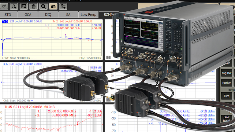
Network Analyzers

Noise Figure Analyzers
In modern communication systems, especially those handling weak signals, the noise introduced by system components can obscure the desired signal, making it crucial to measure and manage noise figure (NF). The noise figure is an important parameter that quantifies the degradation of signal-to-noise ratio (SNR) as the signal passes through various system components, such as pre-amplifiers, mixers, and IF amplifiers. By controlling the noise figure and gain of individual components, designers can directly influence the overall system’s performance, ensuring that weak signals can be detected and processed effectively. This makes it essential for designers to measure the noise figure of each component within the receiver front end, as it provides valuable insights into the system’s ability to handle low-level signals without introducing excessive noise.


To measure the noise figure of devices under test (DUTs) at microwave frequencies, the Y-factor technique is commonly employed, which utilizes a noise source to compare the signal-to-noise ratios of the DUT at different temperatures. This method can display both the noise figure and gain of the system up to 26.5 GHz, and specialized noise sources can extend the measurement range up to 50 GHz. Accurately quantifying noise figure is crucial for ensuring the sensitivity and reliability of the system, as it directly impacts parameters like bit error rate (BER) and overall system performance.
In phase noise measurements, a similar principle is applied. A mixer is used to down-convert the millimeter-wave signal to a lower frequency, typically DC, where phase noise can be more easily measured. Phase noise is a critical parameter in many high-frequency applications, including communication systems and radar, as it affects signal clarity and the accuracy of the system. By precisely measuring phase noise at these high frequencies, engineers can assess the impact of noise on signal integrity and optimize the performance of the entire system.
Millimeter Wave Test Trade Offs
At millimeter-wave frequencies, calibration of test equipment such as vector network analyzers, vector signal generators, and vector signal analyzers is crucial for achieving precise measurements. The accuracy of these measurements can be further enhanced by using slower sweep speeds and increasing the number of measurement points, which help reduce error margins. Additionally, the noise floor of the test instrumentation must be at least 10-15 dB better than that of the device under test (DUT) to ensure clear, reliable readings. Another key factor is the maximum input power; the test equipment must be capable of handling the DUT’s output power without introducing harmonic distortion, which could compromise the integrity of the measurement.
The dynamic range of the measurement system should exceed the DUT’s by at least 20 dB to account for any variations and provide accurate results. Measurement uncertainty is an inherent aspect of any testing process, and it needs to be carefully considered, as it influences the precision of the results. Achieving low uncertainty typically involves longer measurement times, which can be necessary when increasing averaging or lowering the intermediate frequency (IF) resolution bandwidth. These trade-offs must be balanced to optimize both the accuracy and efficiency of millimeter-wave testing.
Connector technology
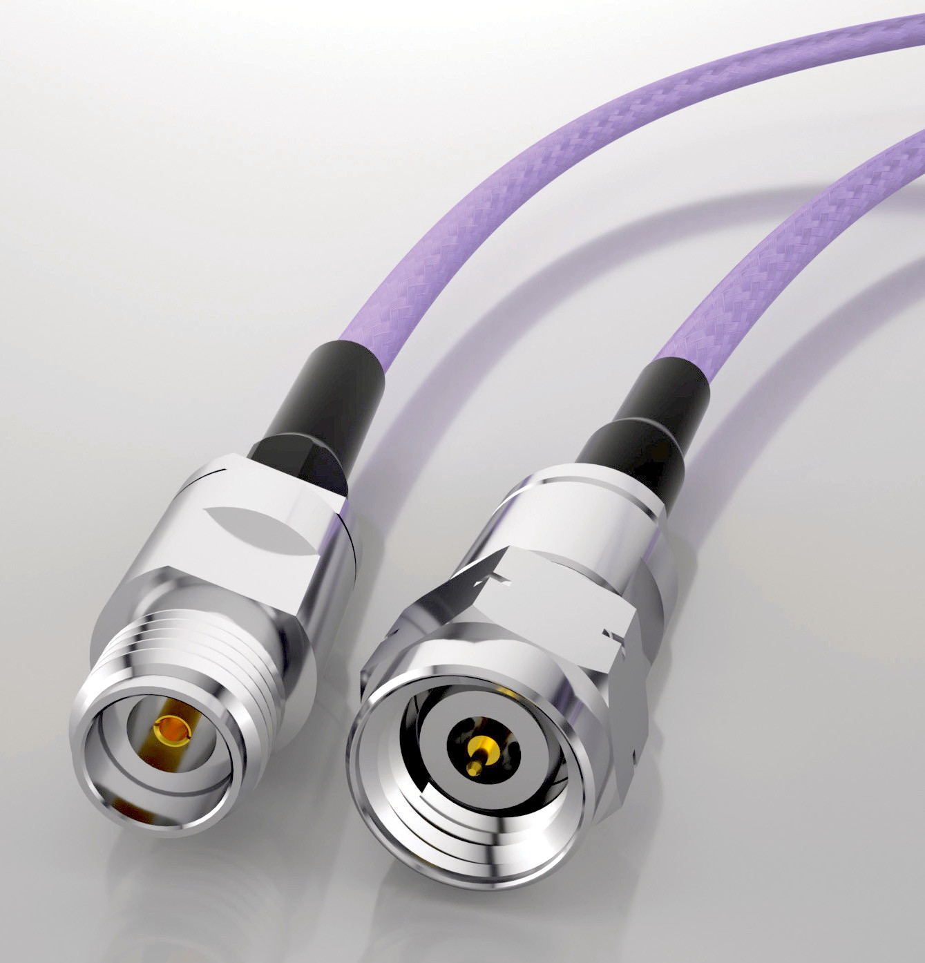
At 70 GHz, the diameter of the coaxial center connector is just 1/2 mm (20 thousandths of an inch), and the center pin diameter is similarly small. At such microscopic scales, even minute imperfections like scratches or dust particles on the connector interface can significantly disrupt the impedance match, leading to measurement errors. The precision required for these connectors is so fine that the dimensions are approaching the limits of what can be achieved in machine shops. As a result, handling millimeter-wave connectors demands extraordinary care. It is essential to inspect connector interfaces with a microscope and clean them before each use to prevent contamination. Connectors should also be tightened using a torque wrench to the specified torque limit, typically around 8 in-lbs, to ensure a proper connection without over-tightening.
Minimizing the number of connections in a test setup helps reduce potential points of failure and the risk of measurement errors caused by dirt or debris, which can adversely affect the return loss of a connection. Fewer connections also reduce the chances of introducing imperfections that could lead to variations in the system’s impedance from the nominal 50 ohms. Each connection, from male to female connectors, adds a layer of uncertainty to the measurement process. Therefore, careful handling and maintenance of millimeter-wave connectors and cables are crucial for ensuring accurate measurements.
In addition to careful connector management, rectangular waveguides are often preferred for millimeter-wave applications due to their inherently low-loss properties. In these waveguides, the electromagnetic field typically propagates in the transverse electric dominant (TE10) mode. This propagation mode has a cutoff frequency, below which the wave does not propagate, ensuring efficient transmission of signals.
Measure as close to the DUT as possible
To improve system performance, precision, low-loss cables are often used, but even high-quality cables introduce uncertainty due to mismatch and insertion loss. A 2-foot long precision test cable can cost over a thousand dollars, yet it still adds uncertainty. The situation becomes more complex when multiple cables are used in a system, and fixed values for correcting loss measurements are applied across the board. For instance, if one cable has 5 dB of insertion loss at 30 GHz and 8 dB at 70 GHz, and another cable from the same manufacturer has 5 dB of loss at 30 GHz but 10 dB at 70 GHz, calculating the net loss becomes challenging and imprecise.
The best way to handle this issue is to characterize each cable using a network analyzer to determine the net cable loss at each measurement frequency. However, this process is time-consuming, complicated, and costly. A more straightforward and effective solution is to eliminate the cables altogether by taking measurements directly at the DUT. This method improves sensitivity by 5 dB and reduces measurement uncertainty to approximately ±0.4 dB, offering a more accurate and reliable assessment of the DUT’s performance.
Field Testing Issues
The Need for Scalable, Flexible Test Solutions
As 5G networks continue to evolve and mmWave technologies become more pervasive, the demand for scalable and flexible test solutions will only increase. Engineers need test platforms that can handle a wide range of frequency bands and device configurations, while also maintaining the accuracy and reliability needed for effective testing. By adopting modular and adaptable testing systems, the challenges posed by mmWave frequencies can be mitigated, ensuring that the next generation of mobile devices, networks, and technologies can be fully validated and optimized for real-world performance.
Conclusion: The Importance of Precision in Millimeter-Wave Testing
As mmWave technologies continue to play a pivotal role in 5G cellular networks, Ka-band satellite communications, military radar, and automotive radar systems, the demand for precise testing and measurement techniques becomes increasingly important. Engineers and technicians must rely on advanced testing equipment and methodologies to evaluate the performance of these high-frequency systems in real-world conditions. Through accurate testing, potential challenges such as signal attenuation, environmental interference, and system calibration can be addressed, ensuring that these cutting-edge technologies perform reliably and efficiently in their respective applications. As the world continues to embrace mmWave technologies, the evolution of test and measurement tools will be key to unlocking the full potential of next-generation communication, defense, and automotive systems.
As the technology matures, engineers will continue to develop more effective and efficient test strategies, enabling the full realization of 5G’s high-speed, low-latency capabilities.
References and Resources also include:
https://www.farran.com/application-notes&rdDF=Mmwave-Frequency-Extenders-article.pdf/
https://blogs.keysight.com/blogs/tech/rfmw.entry.html/2021/04/06/every_loss_countsin-0Rr1.html