International Defense Security & Technology Your trusted Source for News, Research and Analysis
Related Articles

In the age of information technology, mobile data communication has become essential due to its convenience. A major role of mobile communication networks is to provide ubiquitous broadband services. Regardless of the actual position of the antenna on earth, it is always possible to make contact with a communication satellite. The challenge arises when the antenna is used on a non-stationary platform, for example, marine communication.
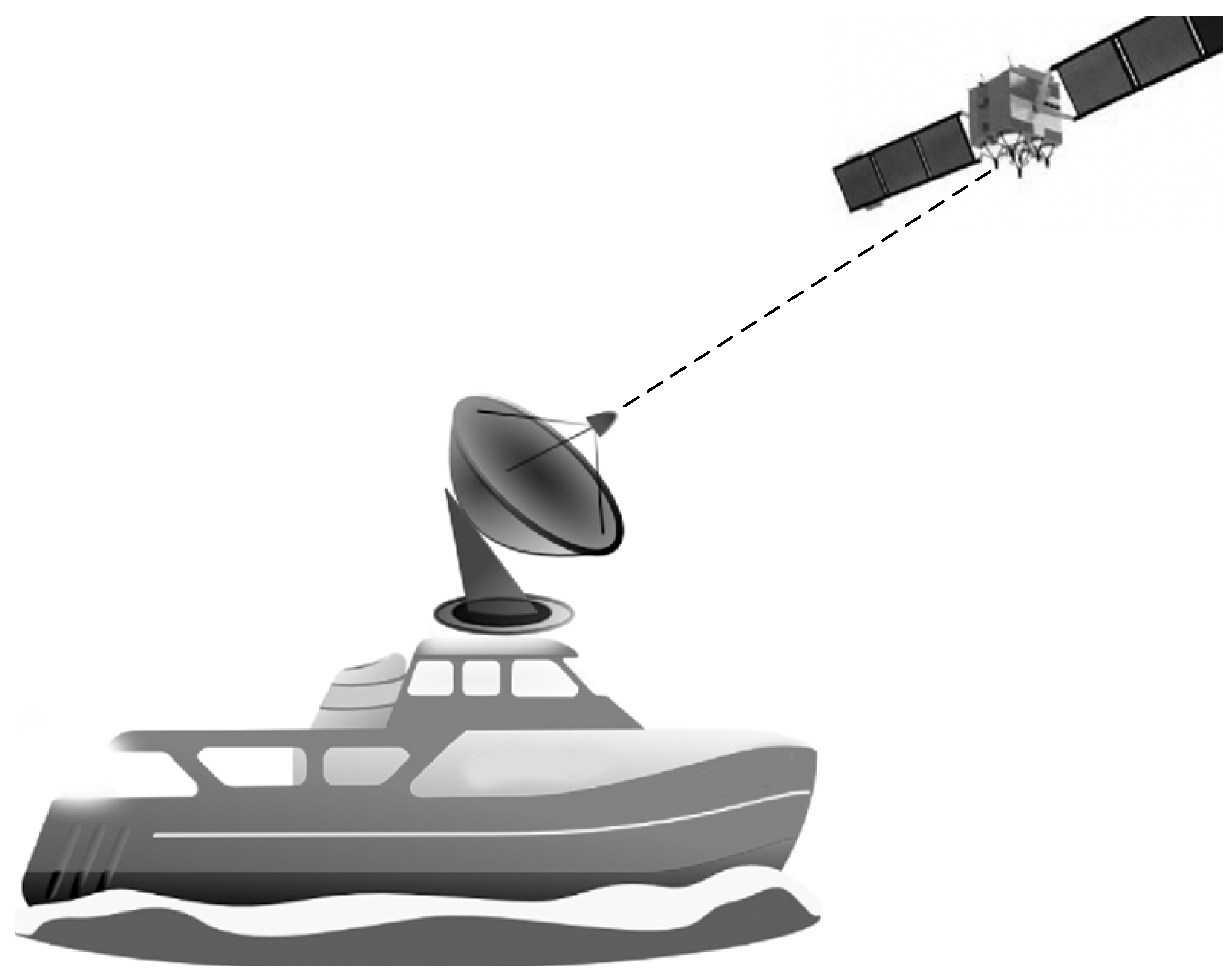
Once the ship-mounted antenna tracks a communication satellite, movements of the ship, mainly due to waves, causes the antenna to point away from the desired position. Disturbance causes roll, pitch, and
yaw motions of the ship as shown in Figure.

Hence, disturbance acting on the ship body breaks the effective communication with the satellite. Therefore, for reliable satellite communications, an antenna and a control system to stabilize the antenna toward the satellite is necessary. A motorized pedestal and control system is used to solve this problem and the antenna can communicate with satellites globally on moving carriers such as ships cars, etc.
Marine Satellite Tracking Antenna (MSTA) is an important shipboard device, which is responsible for establishing the communication between ships and geostationary satellites. The antenna dish of MSTA has to be directed at the geostationary satellite whatever the ship would rotate, due to ocean waves. To guarantee that high-quality satellite signal can be received by theantenna dish, the tracking angle error should be as small as possible.
Now, there are several different kinds of MSTA in the market, such as L-band, C-band and Ka-band MSTA, which are mainly divided according to the frequency range of received satellite signals. For example, the frequency range of the satellite signals received by the L-band and C-band MSTA is typically below 8 GHz, which is a relatively low frequency in field of satellite communication and also means that the tracking angle error of the antenna dish of MSTA can be relatively large, around 2 deg. However, the Ka-band MSTA, as the latest technology of MSTA, requires a high-accuracy tacking system.
For the Ka-band MSTA , the Root Mean Square (RMS) value of tracking angle error should be less than 0.2 deg under the condition that the maximum ship rotation velocity is about 26.2 deg/s. This is becaue the frequency range of the received satellite signals is from 26.5 GHz to 40 GHz, which enables greater volumes of data traffic to be transmitted. There is currently a great need for high bandwidth communication from those latest applications, such as high-definition television and broadband network, which means Ka-band MSTA has a massive market.
The physical characteristics of servomechanical pedestals system generally consist of a structural framework capable of rotational motion
called a gimbal to which an assembly of motors, bearings, gyroscopes, and payload devices are attached. The system adjusts its mechanical position automatically to eliminate the disturbance acting on the carrier and to maintain the pointing direction of the antenna for uninterrupted communication. Two- or three-axis antenna pedestals are used in mobile satellite communication applications.
In general, the common two-axis (azimuth–elevation) pedestal is cheaper, stiffer, and hence more compact than multiaxis configurations. Moreover, since an azimuth–elevation pedestal has a horizon-to-zenith hemispheric coverage, it is the natural first choice. However, the
azimuth–elevation pedestal has the problem of gimbal lock, that occurs when the elevation pedestal gimbal is oriented at 90″ above the horizon. Gimbal lock (singularity of the mechanism) occurs when the line of sight of the antenna dish looks straight up and thus aligned
parallel with the azimuth gimbal control axis. At this position, the pedestal mechanism loses one degree of freedom due to the fact that azimuth gimbal control axis rotation has no effect on the orientation of line of sight.
The singularity condition in the two axis azimuth–elevation pedestal can be alleviated by using an additional gimbal axis An azimuth, cross-level, elevation pedestal is created from an azimuth–elevation pedestal by adding a third, cross-level (xlevel) axis . The fourth axis (the polarization axis) is used to rotate the aperture of the antenna for accurate alignment with polarized signals. It is not used for stabilization purposes. Note that the xlevel axis provides a redundant degree of freedom. However, in the key hole region it provides the additional degree of freedom otherwise missing from the azimuth–elevation pedestal. The stiffness of an azimuth–xlevel–elevation
pedestal is increased by tilting the cross-level axis from the horizontal. This axis is tilted to 30–35″ to achieve increased stiffness with no significant penalty on the performance the system.

The ship-mounted three-axis antenna pedestal is shown in Figure. There are three systems which are arranged one inside the other. Namely, the azimuth control system, the cross-level control system and the elevation control system. The antenna that receives and transmits satellite signals is installed on the elevation subsystem. Subsystems are rotated with the r servomotors to counteract the effect of the disturbance during the motion of the carrier to ensure the pointing accuracy of the antenna towards the selected satellite.
There are three parts in the MSTA under research, that is, the elevation part, cross-elevation part, and azimuth part. A simplified version of Antenna control system block diagram is shown below.
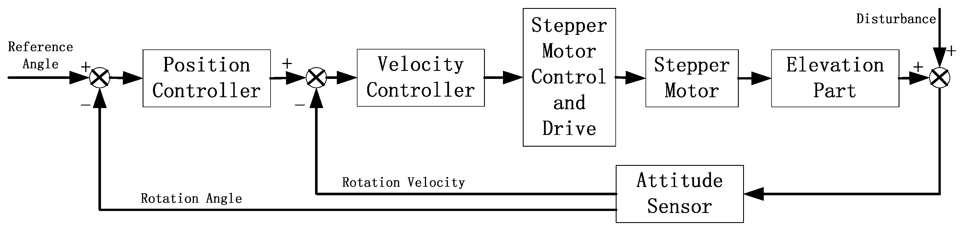
In Figure , there are two control loops, the inner loop and the outer loop. The inner loop is the velocity loop, whose main function is to counteract the velocity disturbance from ships. Most of the disturbance is counteracted by the inner loop and the main focus is put on the design of the velocity controller. The disturbance that cannot be counteracted by the inner loop is left to the outer loop. The outer loop is the position loop and the position controller is a simple PI controller.
Attitude sensor is a key part in the attitude stabilization system, whose main function is to output the current rotation velocity and angle of the antenna dish. It is mounted together with the antenna dish and mainly consists of one Advanced RISC Machine (ARM) chip, and one Inertial Measurement Unit (IMU). The photo of the attitude sensor board is shown in Figure . The ARM chip (Cortex-M7 core) with the CPU frequency of 216 MHz reads sensor data from the IMU module through Serial Peripheral Interface (SPI) bus port. Inside the IMU module, there is one tri-axis gyroscope, one tri-axis accelerometer and one temperature sensor.

The core parameters of the IMU module are listed in Table. The sensor fusion algorithm executed in the ARM chip fuses data from the IMU module and output the current Euler angles of the antenna dish. The running results of the sensor fusion algorithm together with filtered gyroscope measurements are sent out through Universal Asynchronous Receiver/Transmitter (UART) communication port to the motor control and drive board with 1 Mbps baud rate.

Stepper Motor Control and Drive Board
The stepper motor control and drive board is an important part of the attitude stabilization system, whose responsibilities are: (1) executing control algorithm with the frequency of 1 KHz; (2) amplifying the power of the signal from the controller to drive stepper motor; and (3) receiving and sending data to other boards or computers.

The stepper motor control and drive board is shown in Figure . There is one ARM chip (Cortex-M3 core) on this board with the CPU frequency of 168 MHz, which receives data from the attitude sensor board with UART port, runs the control algorithm and sends the controller outputs to stepper motor drive chips through SPI communication port. There are four layers on this board.
The high voltage area on this board typically has a voltage of more than 20 V, while the low voltage area has a typical voltage of 3.3 V. These two areas are connected by a 0 ohm register, which can significantly decrease the electronic current affection from stepper motor. To avoid missing steps in stepper motor, the velocity profile is usually applied. There are many methods to implement the velocity profile by self-written code, but, in our case, a specific stepper motor control chip is applied. That is, the ARM chip sends the command rotation velocity to the stepper motor control chip, which is responsible to convert the command velocity into corresponding pulse, according to
pre-defined velocity profile. The algorithms run in the attitude sensor board and stepper motor control and drive board are firstly designed in Matlab/Simulink, and then converted into C code by the code generation tools.
Most of the work cited above are based on simplified and linearized models. However, the mobile antenna system is typically a multi-input and multi-output nonlinear system with multiple degrees of freedom. The subsystems are affected by the cross coupling effects hence they
have dependent dynamic behavior. Moreover, the antenna is installed on a moving carrier which is a not an inertial frame. The motion of the carrier will exert some dynamic forces on the system. Therefore, if tracking with high precision is required, we need to consider
these subsystems together and establish a more precise model for the whole system.
References and Resources also include:
file:///C:/Users/Laptop/Downloads/Design_and_Implementation_of_Attitude_Stabilizatio.pdf