International Defense Security & Technology Your trusted Source for News, Research and Analysis
Related Articles
A hydrophone is an underwater listening device, just as a microphone is used to detect sound in the air. Hydrophone detects sounds in the water and converts the acoustic energy into electrical energy by detecting changes in pressure in the surrounding environment. Hydrophones listen to sounds in the sea, but do not transmit any sound, making them passive listening devices. The speed and distance at which a sound wave travels through water will be proportional to the pressure changes, which will determine the nature of the electrical output that is transmitted. This device is used in sonar apparatus and in underwater weapons. An array of hydrophones can be used instead of a single hydrophone for the better detection.
The applications of hydrophones typically involve positioning the hydrophone on the seafloor or parallel to a boat under water. Sound waves traveling in from various distances will reach the hydrophone at different times, and this time difference helps locate the source of a signal wave.
Marine environmental research often deploys array hydrophones to track underwater marine life and their behavioral patterns. Underwater surveillance can also be managed using array hydrophones. For example, the US Navy’s sound surveillance system consisting of a series of hydrophone arrays were placed in the Atlantic Ocean in the 1950s to monitor submarine activity during the cold war.
Submarines also use hydrophones to track the position of an incoming, underwater remotely operated vehicle (ROV) to avoid collisions. The hydrophone is placed on top of a submarine, facing down at a 25 to 30-degree angle to allow for accurate tracking of sound. By tracking the location of an incoming boat, the submarine crew can remain in a safe position underwater until the surrounding area is safe enough for the crew to resume to the surface without colliding with an ROV.
Additional applications of a hydrophone include the following: Environmental monitoring, Navigation/positioning systems, Underwater exploration, Towed arrays and Deep ocean operation. Hydrophones are becoming highly useful for tracking patterns of micro-earthquakes and underground volcanic activity. A recent publication by Dziak R.P. et al. (2012) has revealed how the application of ocean-bottom hydrophones helped measure an increase in seismic activity over several years to the point at which a volcanic eruption was observed in April 2011.
Studies have also hinted on the development of an autonomous hydrophone called the Quasi-Eulerian hydrophone, or QUEphone. It is a tether-free floating hydrophone that can maintain an almost fixed position in ocean water and detect acoustic events in near-real time. It can continuously monitor sound and transmit data by repeatedly traveling between the seafloor and the sea surface.
Hydrophone technology
There are two types of hydrophone which are as follows: The Omni-directional type detects sound from all the directions with equal sensitivity. Directional Hydrophones has higher sensitivity to signals in a particular direction. Directional hydrophones are
usually built from scores of Omni-directional hydrophones, but can also be created from hydrophone arrays.
Structure
A hydrophone with a single transducer has a circular conical shape that reflects incoming sound waves which in turn allows the hydrophone to be positioned at varying locations and depth. A Hydrophone works on piezoelectric effect. Piezoelectric effect is the ability of a material to produce an electric charge in response to applied mechanical stress. This transducer is crucial for converting the incoming sound waves into an electrical voltage. So, the output voltage is basically proportional to acoustic pressure input. This technique works really well and also results in the desired flat frequency response up to a level where the piezoelectric crystal begins to have a resonance
A hydrophone comprises a casing within which a conductive substrate is mounted and a piezoelectric crystal (Ceramic or Polyvinylidene Fluoride, PVDF) is mounted on the exterior of the substrate. The conductive substrate increases the mass and limits the ringing at the resonant frequency of the piezoelectric crystal. A piezoelectric crystal is used due to the fact that the acoustic impedance matches with the impedance of the crystal. So, it facilitates its use in underwater applications.

Use of a piezoelectric transducer as an alternative to crystal material is now a popular option in modern-day hydrophone technology. Piezoelectric material is ideal for making hydrophones. They can change their form and help generate an electrical potential in response to mechanical or external pressure changes. When an electrical voltage is applied to the crystalline ceramic material, the crystalline structure aligns, becomes anisotropic, and carries an electrical charge.
The volume between the casing and the substrate is always filled with a liquid. Preferably oil is used. If there is one or more bubbles of air in the volume between the casing and the conductive substrate. It will permit vibration of the substrate and the piezoelectric element.
It is important to remember that sound in water is affected by the temperature of the water. Warm surface water is less dense and so sound traveling through the water to the surface will refract and becomes trapped, a phenomenon referred to as a surface duct.As most hydrophones are used in an open-water environment, they are typically exposed to temperature and pressure variations, and hence, the technology needs to be wired to account for variations and so to provide an accurate picture of sound location.
The sensitivity of hydrophones can be determined by the voltage produced by a hydrostatic pressure wave. A useful parameter in choosing piezoelectric materials to be used in hydrophones is the voltage coefficient, which links the electric field and the applied hydrostatic strain. Another widely used parameter is the hydrostatic strain coefficient, which refers to polarization resulting from changes in stress. Calibration methods such as comparison or substitution can also be applied; however, this method does require calibrating the transducers over a full range of environmental conditions.
Optical Fiber Hydrophone
The fiber optic hydrophone is the next generation of hydrophone technology. A fiber optic hydrophone is a sensor that uses an optical fiber either as a sensing element or as a means for regulating signals coming from a remote sensor to the electronic device that process the signals.
Optical fibers are mostly used in remote sensing which is due to its small size and also no electrical power is required at remote location. Optical fiber sensors are also resistant to electromagnetic interference and do not carry out the conduction of electricity. These can be used in places with high voltage electricity or combustible material.
Optical fiber sensors can be used to bear up high temperatures. The advantage of optical fiber hydrophone is that it can be used to determine temperature and pressure, at the same time and the same point in a measuring environment. This makes a direct correlation between
pressure and thermal change. Hydrophones based on the interferometry method are mostly used. Interferometry is family of techniques in which waves (usually EM waves) are superimposed. It cause the development of inference phenomena which helps in extracting the original
information.
Array Hydrophones
The only problem with a single transducer is that signals from other directions interfering with the main signal cannot be subtracted and this can obscure data about the location of the desired signal. While a hydrophone can detect sound waves in the air, it is not as sensitive with airborne sounds because of its acoustic impedance is designed specifically for sound detection in water.
An array of hydrophones can be used instead of a single hydrophone for the better detection. The Hydrophone array is created by connecting many hydrophones in different but known locations. The sound waves reach different hydrophone at a different instance of time, depending on the origin of the source. The difference between the sound arrival time intervals can be used to calculate the direction that the sound is coming from. Simple arrays with only two hydrophones can be used to detect the origin of the sound.
Array hydrophones (streamers – built of multiple transducers) are all wired to receive a large sound signal collectively. The transducers are packed together in a tube with oil, which aids the collection of pressure waves entering the hydrophone. Pre-amplifiers are often used to enhance the electrical signal and limit the potential of noise contamination from additional components to the hydrophone.

Arrays work more efficiently than single hydrophone because they are able to filter out most of the noise from the other directions. This arrangement also increases the signalto-noise ratio, which allows us to hear hard to detect signals. A hydrophone array is used in most of the sensors to detect acoustic sounds.
Towed arrays and variable depth sonars, together with hull-mounted sonar
Arrays of hydrophones have been part of Navy sonar systems for over fifty years now. They are used both passively and actively and now are quite sophisticated. These arrays were used in fixed configuration such as the SOSUS system and towed arrays deployed from surface ships and submarines.
The UMS 4110 hull-mounted sonar for large surface ships combines passive, anti-torpedo and obstacle-avoidance modes. For smaller vessels, the Kingklip hull-mounted sonar offers an excellent balance between performance and space requirements.
A special kind of SONAR is used by ships to overcome the problem of flow noise; they are known as towed SONAR. Torpedoes are also equipped with active and passive SONARs to guide them directly and accurately to the target.
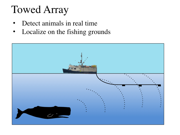
Towed Arrays have been common place amongst the major navies for many decades and are a key sensor in a naval vessel’s capability in the detection, tracking and classification of other vessels. They provide numerous advantages over hull mounted sonars such as variable
depth, lower frequency beamforming, greater detection ranges, and reduction in the effect of own ships noise. These advantages are mainly due to the length of a Towed Array’s acoustic aperture being longer than the towing vessel and positioned at the end of a long tow cable. The large aperture possible with large number of sensors assembled at relatively larger /2, promises better range. Towed arrays are one of the well sought out technologies meant for getting better immunity from own ship noise because of towing the array far behind the towing ship.
Towed array combines a host of technologies, viz., packaging large number of sensors into a proper deployable casing, deployment from a moving platform, and digitisation and telemetry of acoustic and non-acoustic sensor data
The towed arrays and variable depth sonars, together with hull-mounted sonar, are the main elements comprising naval surface ship sonar fits today. Dunk bodies housing transducers and associated electronics are dipped from helicopters for detection of sub-surface targets. These requirements have posed new challenges in sonar technology development related to winches and towed bodies. Development and characterisation of exotic materials for sonar systems in various areas like composite materials, nanomaterials, baffles, encapsulants, etc., are important for improved reliability and enhanced life of transducers and interconnect materials.
To offset the adverse effects on detection by the bathymetric profile of the ocean and self-noise of the platform, the deployment mechanisms of sonar transducers have undergone changes to maximise the detection range. Though the hull-mounted and bow mounted transducers are the most common approaches, the variable depth towed array sonars also help in detection of targets and torpedoes below the surface-sound channel.
Seabed arrays are off-board passive sonars, which can be deployed on the seabed for monitoring strategic locations at sea on a continuous basis to assess the threats from submarines and submersibles A seabed system with capability to detect multiple targets around 360 without any left/right ambiguity and end-fire anomaly, has been developed and proven for performance. Multiple-arrays deployed with appropriate spatial separation will facilitate the passive range estimation of the target too. The system consists of multiple linear hydrophone arrays with a data acquisition system The data can be transferred to a processing station at the coast.
Towed Array Technology
A hydrophone is the primary sensor in a Towed Array, which when multiples are configured in a straight line enables acoustic beamforming by the sonar processing system. Typical line array hydrophones contain large piezoelectric ceramic devices so as to provide high
sensitivity and minimize any pre-amplifier electrical gain requirements. A low pre-amplifier gain is driven by the necessity for low pre-amplifier electrical self-noise to ensure the hydrophone pre-amplified output is lower than the equivalent ambient acoustic noise.
Traditional Towed Arrays are large oil filled Polyvinyl Chloride (PVC) or Polyurethane (PU) hoses which can exceed 600m in length and measure between 30mm and 90mm in diameter. Contained within the hose are hydrophones and Non-Acoustic Sensors (NAS) to
provide acoustic, heading and temperature sensing. The weight and volume of traditional Towed Arrays requires large manned vessels to tow an array along with bulky handling systems, which tends to lead to bespoke ship design. This has previously limited Towed Array
operations to vessels such as Frigates and conventional Submarines, which are costly assets to purchase and operate, particularly for the required duration associated with ASW deployments.
In 2010, Systems Engineering and Assessment (SEA) Limited developed its first generation low power, configurable digital Thin Line Towed Array (TLTA) named KraitArray. KraitArray’s small 16mm diameter and up to 50m length results in a considerable reduction
in weight and volume, enabling smaller vessels such as Offshore and Inshore Patrol Vessels (OPV/IPV) and Unmanned Vessels to host and deploy an ASW Towed Array capability, explains Chris Tucker – Product Technical Authority for KraitArray at SEA.
The original KraitArray contains up to 32 low power, low noise hydrophones, each digitised by a bespoke small scale, low power, high performance digitisation system known as the Micro Digital Acquisition and Source System (μDASS). To aid array shape estimation and
environmental sensing, up to eight sensors known as the Micro Non-Acoustic Sensor (μNAS) can be fitted to KraitArray to provide heading, pitch, roll, temperature and depth measurements.
Since KraitArray’s launch in 2010 it has been integrated with and operated from a variety of vessels including small research vessels, rigid inflatable’s and more than five types of unmanned vessel. Building upon the success of the first generati on KraitArray, in 2018 SEA developed and launched KraitArray Version 2 (v2) which provides the user with up to 192 hydrophones and an increased acoustic aperture
length of up to 150m. These advancements increase the overall detection range of KraitArray v2 and the ability to listen for and localise lower frequency targets compared to that of the first generation KraitArray.
KraitArray’s small diameter minimizes the physical system footprint, which in turn reduces or removes the necessity for large handling systems while also reducing hydrodynamic drag forces. Many design challenges were faced during the development of both generations of
KraitArray, however through the through the use of Commercial-offthe-Shelf (COTS) technology SEA has overcome electrical, mechanical and acoustic engineering challenges. The Strain Member, Hydrophone, Digitisation System and Module Interconnect all posed significant challenges during KraitArray’s design.
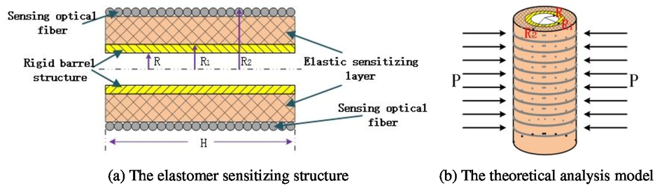
Strain Member
A Towed Array Strain Member provides the mechanical backbone which extends the length of the array and allows precise mounting of sensors and components. Due to the hydrodynamic drag forces induced during towing which are transferred via the hose and internal components to the strain member, the strain member requires high tensile strength and low elasticity.
ASW operations are performed at low tow speeds by the towing vessel to minimize self-noise and avoid detection; therefore there is minimal difference in hydrodynamic drag force. At high speeds the hydrodynamic forces transferred to the Towed Array Strain Member and subsequently the tow vessels point of tow increase significantly. An array capable of only low tow speeds would impact the towing vessels
manoeuvrability, particularly when evasive manoeuvres are required.
Testing and selection of KraitArray’s strain member has led to the use of a high tensile strength, low creep material which fits within the small space envelope of the hose, ensuring KraitArray can survive greater than 28 knot tow speeds it may be subjected to during
deployment.
Hydrophone
A hydrophone is the primary sensor in a Towed Array, which when multiples are configured in a straight line enables acoustic beamforming by the sonar processing system. Typical line array hydrophones contain large piezoelectric ceramic devices so as to provide high
sensitivity and minimize any pre-amplifier electrical gain requirements. A low pre-amplifier gain is driven by the necessity for low pre-amplifier electrical self-noise to ensure the hydrophone pre-amplified output is lower than the equivalent ambient acoustic noise.
In order to minimise KraitArray hose diameter, SEA have developed a new low noise, high gain pre-amplifier to allow the piezoelectric ceramic size reduction. Dimension restrictions challenged both the electronic preamplifier and associated mechanical mounting arrangement design. Through the use of the latest 3D printing technology and leading electronic design capabilities, an acceleration cancelled hydrophone with attached miniaturised low-power low-noise pre-amplifier has been designed.
During KraitArray v2 development the pre-amplifier design was revisited to reduce the noise floor to below Knudsen Sea State Zero and include a Built-In-Test (BIT) function to confirm pre-amplifier functionality when installed in the array.
Digitisation System
An array digitisation system housed within a Towed Array provides many advantages such as signal multiplexing with reduced noise susceptibility, and reduced number of electrical conductors, aiding overall array performance and the ability to package electronics
and wiring inside a small diameter hose.
In KraitArray first generation the μDASS was located at the head of the array due to it’s larger than 16mm diameter. The low power digitisation system provided 32 simultaneously sampled 24bit Analogue-to-Digital Converter (ADC) channels with 120dB dynamic range.
This allowed for up to 32 hydrophones to be installed in the array with the digitised data output over the User Datagram Protocol (UDP) Ethernet interface, allowing the user to easily integrate KraitArray into new or existing sonar systems.
Locating a digitisation system at one end of an array means any additional hydrophones requires extra signal cables, which in turn increases the number of electrical conductors within an already limited space envelope. It also means any inter-module electromechanical
connectors require increased contacts which inevitability increases the connector dimensions.
KraitArray v2 addresses these limitations by distributing a 24bit simultaneous sampled, 120dB dynamic range digital sampling system within the KraitArray hose. A series of digitisation nodes connected to a common digital backbone running throughout the length of the array allows up to 192 hydrophones to be distributed and sampled over up to 150m.
Module Connector
To manufacture arrays longer than 50m an array must be manufactured in sections, introducing a requirement for a watertight electromechanical connector. Increasing the length of an array and its acoustic aperture allows for increased hydrophone counts, which in turn increases the array’s Directivity Index (DI) as well as the ability for lower frequency beams to be created in the sonar processing, resulting in greater detection ranges of the Towed Array system.
Distribution of the KraitArray v2 digitisation system and the introduction of a digital backbone mean the required number of electrical connections is minimised and remains fixed as the number of hydrophones and modules increase. This has led to SEA developing a
bespoke watertight connector rated to 500m depth which is scalable down to 16mm diameter to match the array hose diameter, creating a seamless interconnect between KraitArray modules. The connector development posed many electrical and mechanical challenges to ensure all required signals and power are passed from module to module as well as surviving the tow loads likely to be seen during deployment
References and Resources also include:
https://www.azosensors.com/article.aspx?ArticleID=13
https://www.udt-global.com/__media/libraries/platform-design/82—Chris-Tucker-Paper.pdf
https://www.ijert.org/research/a-review-paper-on-hydrophones-IJERTCONV5IS23015.pdf