 International Defense Security & Technology Your trusted Source for News, Research and Analysis
Related Articles

The growing demand for high-efficiency fighter aircraft, commercial airbuses and the ever-evolving Aerospace and Defense requirements are driving the demand for next-gen airborne electronics systems. Air transportation agencies and aviation OEMs across the globe have been striving to build next-generation Airborne electronics systems to make flying more reliable, predictable, and safer.
Airborne electronics such as communication systems, transmit-receivers, guidance & navigation systems, flight control computers, and fire-control systems among others are some of the critical components of an aircraft. The design of Airborne electronics systems and sub-systems demands higher safety and reliability to ensure airworthiness of these sub-systems. All major avionics OEMs, R&D and System Engineering companies designing airborne electronics hardware and software have to ensure compliance with several regulatory standards like DO-254, DO-178B/C, ARINC, MIL-STDs, and DO-160 to develop high performance, reliable products.
Airborne Electronics – Standards
DO-254 – Design Assurance Guidance for Airborne Electronic Hardware
DO-254 is a stringent functional safety standard that defines and regulate the process of auditing and certification of Airborne electronics systems. DO-254 is published by Radio Technical Commission for Aeronautics (RTCA) in 2005 and administered by the FAA to ensure safety in electronic-airborne systems. The standard insists on tracking the developmental activities and documenting every step and each stage involved. The standard helps minimize errors in the process of a design and brings traceability to a great extent.
DO-254 covers the guidance for airborne electronics hardware such as,
- Line Replaceable Units
- Circuit board assemblies
- Programmable components such as field-programmable gate arrays (FPGA), programmable logic devices (PLD), and application-specific integrated circuits (ASIC)
- Commercial off-the-shelf (COTS) modules.
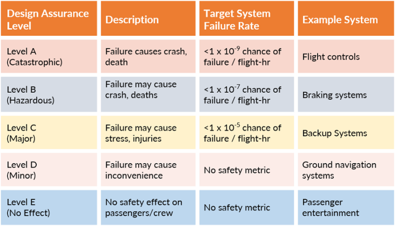
DO-254 defines five levels of compliance, based on the impact of hardware failure on the aircraft or its functions. Level A, being the most stringent (termed as catastrophic), and Level E with least impact (termed as No safety) on passengers/crew. This implies, meeting Level A compliance for airborne electronics systems requires a very complex process of verification and validation than Level E compliance.
DO-254 covers the following aspects of Airborne electronics Hardware design processes
• Requirements Capture
• Conceptual Design
• Detailed Design
• Implementation
• Verification
• Transfer to production
RTCA DO-160G
Vital airborne electronics systems must be designed to withstand diverse environmental conditions it may subject to during the flight. To standardize the design, production and testing of these complex, classified aircraft electronics, in 1980, RTCA published DO-160 – Environmental Conditions and Test Procedures for Airborne Equipment.
RTCA DO-160G provides a set of minimal standard environmental test conditions (categories) and corresponding test procedures for testing airborne equipment for the entire spectrum of aircraft from light general aviation aircraft and helicopters through the jumbo jets and supersonic transport categories (SST) of aircraft.
The purpose of these tests is to provide a controlled (laboratory) means of assuring the performance characteristics of airborne equipment in environmental conditions similar of those which may be encountered in airborne operation of the equipment. The standard environmental test conditions and test procedures contained within the standard, may be used in conjunction with applicable equipment performance standards, as a minimum specification under environmental conditions, which can ensure an adequate degree of confidence in performance during use aboard an air vehicle.
The standard covers testing of a wide range of critical factors such as temperature, humidity, electrical interference, shock resistance, flammability, magnetic effect, waterproofness, radio frequency susceptibility, lightning direct effects and operational shocks among others, that can impact the performance of an airborne electrical or electronic device. By subjecting airborne electronics to DO-160G certification and testing process, the equipment confirms to deliver reliability, accuracy and robustness in any flight condition.
The document includes 26 Sections and three Appendices. Examples of tests covered include vibration, power input, radio frequency susceptibility, lightning and electrostatic discharge. Coordinated with EUROCAE, RTCA DO-160G and EUROCAE ED-14G are identically worded. RTCA DO-160G is recognized by the International Organization for Standardization (ISO) as de facto international standard ISO-7137.
| Section | Name | Description |
|---|---|---|
| Standard conditions | ||
| 4.0 | Temperature | This checks the effects of temperature on the system. Condensation also can be a factor coming from cold temperatures. It includes
|
| Altitude | These tests check the effects (in terms of performance) of altitude, including loss of cabin pressure on the device/system/equipment. Factors tested include dielectric strength, cooling under low pressure, and resilience to rapid change in air pressure. The norm defines the different temperature profiles under which the equipment must be tested. Due to the variety of aircraft, the equipment are classified in categories. | |
| 5.0 | Temperature Variation | These tests exercise the assemblies capability of surviving extreme temperature changes and the effects of differing coefficients of thermal expansion. |
| 6.0 | Humidity | These tests under humidity check the effects of high concentrations of humidity and the articles ability to withstand moisture effects. Typically moisture sensitive devices have issues with this test and require a conformal coat or other types of protection. |
| 7.0 | Shock & Crash safety | This aircraft type-dependent test checks the effects of mechanical shock. Crash safety test insures the item does not become a projectile in a crash. The norm describes the test procedure for airborne equipment. |
| 8.0 | Vibration | Aircraft type-dependent test checks the effects of vibration and the equipment’s ability to operate during all vibration scenarios. |
| 9.0 | Explosion Proofness | These tests subject the test article to an environment under vacuum, with a gaseous mixture of combustibles. The unit must operate and be subjected to any actuation including knob turns and button pushes and not ignite the environment. |
| 10.0 | Waterproofness | These tests subject the test article to various scenarios of dripping water or pooled water to verify the unit will fully operate in the given condition. |
| 11.0 | Fluids Susceptibility | Aviation-related fluids susceptibility including a variety of fluids ranging from carbonated sugared beverages to various cleaners and solvents. |
| 12.0 | Sand and Dust | These tests subject the unit to an environment of blowing sand and dust of specific particle sizes in which the unit must operate at the end of exposures. |
| 13.0 | Fungus Resistance | These tests determine whether equipment material is adversely affected by fungi under conditions favorable for their development, namely, high humidity, warm atmosphere and presence of inorganic salts. |
| 14.0 | Salt & Fog | This test verifies the test articles’ ability to survive multiple exposures of salt fog and drying and the environment’s ability to cause accelerated corrosion. |
| 15.0 | Magnetic effect | This ensures that the aircraft’s compass is not affected. |
| 16.0 | Power input | Input power conducted emissions and susceptibility, transients, drop-outs and hold-up. The power input tests simulate conditions of aircraft power from before engine start to after landing including emergencies. |
| 17.0 | Voltage Spike | This test determines whether equipment can withstand the effects of voltage spikes arriving at the equipment on its power leads, either AC or DC. |
| 18.0 | Audio Frequency Conducted Susceptibility | This test determines whether the equipment will accept frequency components of a magnitude normally expected when the equipment is installed in the A/C. These frequency components are normally harmonically related to the power source fundamental frequency. |
| 19.0 | Induced Signal Susceptibility | This test determines whether the equipment interconnect circuit configuration will accept a level of induced voltages caused by the installation environment. This section relates specifically to interfering signals related to the power frequency and its harmonics, audio frequency signals, and electrical transients that are generated by other onboard equipment or systems and coupled to sensitive circuits within the EUT through its interconnecting wiring. |
| 20.0 and 21.0 | RF emission and susceptibility | Radiofrequency energy: — radiated emissions and radiated susceptibility (HIRF) via an (Electromagnetic reverberation chamber). |
| 22.0 and 23.0 | Lightening susceptibility | Direct and indirect effects depending on mounting location; includes induced transients into the airframe or wire bundle. |
| 24.0 | Icing | This test determines performance characteristics for equipment that must operate when exposed to icing conditions that would be encountered under conditions of rapid changes in temperature, altitude and humidity. |
| 25.0 | ESD | This checks for resilience vs ESD in handling and operation. |
| 26.0 | Flammability | This analysis and test verify the assembly will not provide a source to fire. |
ARINC 661 – Development of Cockpit Display Systems
Aircraft cockpit displays are becoming increasingly complex over the past two decades due to the stringent certification requirements defined by DO-178B/C. ARINC 661 is a set of specifications that encourage a standard, flexible architecture for the avionics cockpit systems. ARINC 661 outlines the specifics for Cockpit Display Systems (CDS) and the communication between CDS and User Applications (UA), which control and monitor airborne electronics and subsystems. The standard was first published in 2001 and over years it has evolved adding several supplements such as widgets for vertical maps, Multitouch management, Animated graphics, 3D maps, improvements in user interface, etc.
ARINC 661 also outlines GUI definition for CDS. The standard brings out a clear separation between graphics codes, logic codes and the layout of all visual elements. ARINC 661 brings out a standard communication protocol for the CDS and UA to exchange messages.
Modern cockpit designs are increasingly adopting the ARINC 661 Standard. The standard is used right from requirements specification, design, and development through deployment and maintenance of airborne display systems. The objective of the standard is to efficiently manage the increasing complexity of Cockpit Display Systems. The standard aids easy integration of new avionic systems, display functionalities and Cockpit HMI upgrades into aircraft in business – all while minimizing the cost implications.
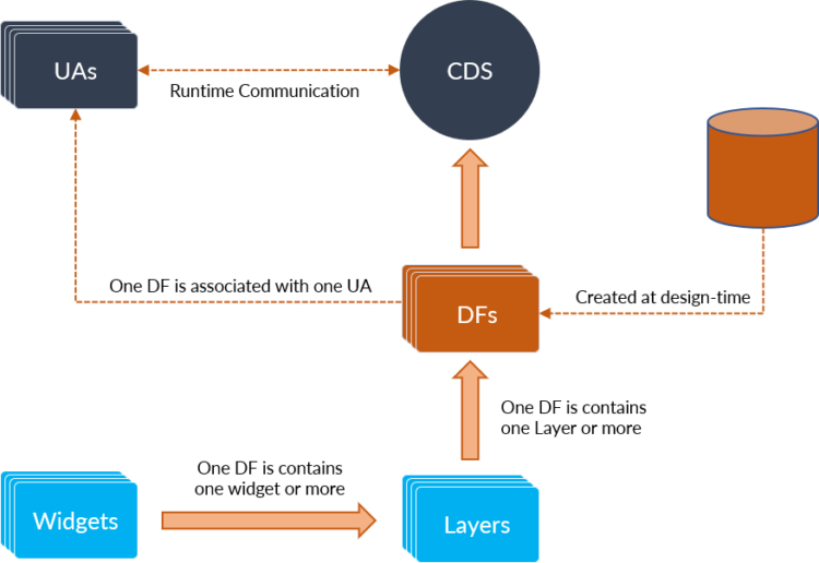
• Cockpit Display System – Graphics Server that displays and manage the GUI
• User Application – System application interacting with the CDS
• Definition File – GUI definition associated with User Application
• User Application Layer – GUI container for widgets, the basic building block of the GUI
MIL-STD-704
MIL-STD-704 deals with the electric power characteristics of an aircraft and defines a standardized power interface to ensure compatibility between the aircraft power system and airborne electronics. The standard addresses various power characteristics such as voltage, frequency, phase, power factor, ripple, maximum current, electrical noise and abnormal conditions for both AC and DC systems in an aircraft. Published in 1959, MIL-STD-704 supersedes the engineering document MIL-E-7894 describing aircraft electrical power.
MIL-STD-704 outlines several distinct operating conditions for an aircraft electrical system such as normal operation, power failure, engine starting, abnormal electrical power, power transfers, etc. Any airborne electronics equipment designed should address these operating conditions and meet the performance criteria defined depending on its criticality.
Developing airborne electronics systems and sub-systems from scratch involves a tremendous amount of effort, time and cost. Employing safety-certifiable COTS airborne electronics hardware modules in avionics designs enables the developers to kick-start the project faster. In addition, the use of safety-certifiable COTS modules helps the developers efficiently manage the challenges of several regulatory requirements such as documentation, component certification and risk mitigation. Thus, safety-certifiable COTS modules and systems significantly reduce development time, cost, and overall certification efforts.
