 International Defense Security & Technology Your trusted Source for News, Research and Analysis
Related Articles

The drones have emerged as a major new threat to civilian infrastructure and military. Counter-drone technology, also known as counter-UAS, C-UAS, or counter-UAV technology, refers to systems that are used to detect and/or intercept unmanned aircraft. One of the attractive Anti-drone weapons have been directed energy weapons (DEWs) both of electronic type and laser weapons. Thus, today’s laser weapons are meant to defend against swarms of inexpensive mortar rounds, drones and other projectiles, and are intended to be mounted on platforms which are mobile and self-contained (meaning they may not have ready access to an external source of power). C-RAM (Counter Rocket, Artillery and Mortar) systems intended to be deployed in the battlefield to protect troops and equipment from incoming projectiles. Currently, these are envisioned to be single, vehicle mounted lasers, with output powers in the 10 kW to 50 kW range.
Boeing has already successfully prototyped such a system, which they call the High Energy Laser Mobile Demonstrator (HEL MD). This consists of a 10 kW solid state laser installed on an Oshkosh Tactical Military Vehicle, along with all the necessary targeting and control systems. HEL MD has proven the ability to lock on to and destroy a mortar round of about 10 inches in length, traveling at hundreds of miles per hour, from several miles out. The system is also effective against Unmanned Aerial Vehicles (UAVs or drones); in this case, it may be sufficient to damage the drone’s navigation and targeting systems, rather than completely destroy it.
A laser destroys targets with pinpoint precision within seconds of acquisition, then acquires the next target and keeps firing. Another major component of the HEL MD is the beam director which will provide full sky coverage and engage below-the-horizon targets. As technology matures, higher power lasers will integrate with improved pointing and tracking capabilities to extend range and increase system effectiveness. The system’s beam controller was mounted to the top of the vehicle while the laser itself, the power and coolant, were integrated into the interior of the Stryker.
Laser DEW Technologies
U .S . Army Space and Missile Command designed High Energy Laser Mobile test truck, reported in 2016. Key HELMTT features are:
Army’s first mobile high energy solid-state laser platform
Rugged beam control system
Modular building block approach
Speed-of-light engagement of threats with pinpoint precision
Demonstrated lethal effects on small caliber mortars, unmanned aerial systems (UAS), and ground targets, as well as potential intelligence, surveillance, and reconnaissance capability
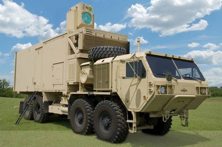
Figure. USASMDC/ARSTRAT’s High Energy Laser Mobile Test Truck
2. The HELMTT, formerly the High Energy Laser Mobile Demonstrator, was a technology integration and demonstration effort with a solid state laser system, agile beam control system, and supporting subsystems integrated into a large tactical vehicle. The goal is to integrate and
demonstrate maturing technologies to the point where lethal engagements in a relevant environment can be demonstrated. The Heavy Expanded Mobility Tactical Truck-based HEL MD became HELMTT when the Army decided in early fiscal year 2016 to integrate a
smaller laser system on a family of medium tactical vehicles. The system was designated the HEL Tactical Vehicle Demonstrator. HELMTT provides risk-reduction for Army high energy laser development.
3. The High Energy Laser Mobile Test Truck efforts support development of future deployed high energy laser systems capable of executing missions such as: force protection, counter-UAS,
These subsystems include: laser subsystem (LSS); beam control subsystem (BCS); electrical power subsystem (EPS); thermal management subsystem (TMS); and Battle Management, Command, Control, Communications and Intelligence (BMC4I) subsystem. These subsystems will be integrated into a modified Family of Medium Tactical Vehicles (FMTV).
• Compact efficient lasers with excellent beam quality
• Advanced Adaptive Optics to compensate for atmospheric effects
• Enhance tracking sensors for target acquisition and track
• Compact non-traditional laser cooling
• Low SWaP, high capacity electronics / processors for CubeSat /MicroSat application

The HELMTT consisted of a 10 kW laser projected through a precision pointing, high-velocity target tracking beam control system. To support the laser and beam control system, the HELMTT has power and thermal management systems that power and cool all the subsystems. A Battle Management, Communications, Command and Control subsystem receives target cues from radars and points the laser
beam to engage the targets. During the course of the events in 2016 , HELMTT shot down Group 1 UAS rotary-wing and fixed-wing targets. It also destroyed ground targets.
Stabilized Platform and Technologies
Electro-optic systems and sensor designers today are often asked to take their system “on the road” (or on the sea or in the air) as customers increasingly look for on-the-move operation. Electro-Optical tracking systems are very vital for surveillance, target acquisition and engagement in battle field. They facilitate wide area surveillance with limited field-of-view electro-optical sensors. Inertially stabilized platforms (ISP) are used to aim and stabilize many different instruments. These can include infrared and optical cameras used for civilian or military applications including target tracking, telescope pointing, and image capture where the line of sight (LOS) of the instrument must be held steady and pointed to a desired location.
This becomes even more essential if the instrument is mounted to a moving base such as a land vehicle, airplane, helicopter, or a moving ship under environmental vibrations. Adapting a camera or other sensing system from “fixed” mounted use to mobile use is a daunting task that requires addressing a number of considerations, including vibration tolerance, power supply issues, and stabilization. On-the-move operation requires any directional sensor, such as a camera, to remain pointed in the desired direction while the vehicle is moving.
Laser pointing accuracy and pointing stability are defined as an angular value, usually in milli- or microradians (mr or μr). Pointing accuracy is simply whether the laser points where it is supposed to. Pointing stability is a measure of how much the beam position drifts from the ideal target over time. Stability can be affected by a number of factors, internal and external to the laser itself, including physical motion, heat buildup, cavity instability, air currents, and many more. There are actually two components to laser pointing and laser pointing stability, linear and angular, which combine to affect the beam’s position. The linear component comes from the horizontal and vertical motion of the laser, perpendicular to the axis of propagation. Call this X and Y. This is the motion that one sees when the laser is raised or lowered, translated right or left, or is subjected to some type of vibration. This motion is normally 1:1, that is, if the laser is raised 1mm, the spot moves 1mm unless there is a magnification lens in the optical path. The angular component is the tip or tilt of the laser beam altering the path from the parallel. We call this dθx or dθy.
The ability to stabilize a system and hold its LOS depends on many factors including, but not limited to, the control algorithms used, the gain settings of these algorithms, and the quality of the sensor providing the measurements used to control the LOS. Any ISP system includes integration of complex instrumentation; the model also needs to address the internal vibrations of the electromechanical system and external
disturbances from the environment that can get challenging for simulations.
This stabilization function from moving platforms such as aircraft, boats, and ground vehicles, has in the past typically been provided by “gimbals, ”which integrate a sensor suite into a highly engineered system that provides stabilized pointing, usually along with other functions like video tracking, targeting, etc. Gimbals are highly integrated camera systems that provide stabilized pointing and control as well as advanced features such as video tracking, targeting, radar slew-tocue and more. Gimbals offer unparalleled performance and highly integrated feature sets. However, this performance comes at a cost both in terms of money, as well as in terms of flexibility. Designers now have another option. Advances in lower-cost MEMs-based gyros, microprocessors, and high-performance pan/tilts have resulted in stabilized pan/tilt robotic platforms that provide a modular, lowcost, stabilized pointing capability for a wide range of on-the-move sensing applications.
Mechanical stabilization approaches involve physically moving the entire camera system to counteract the motion. There are two
general categories of mechanical stabilization:
• Passive – using counterweights or large gyroscope to physically counteract the motion.
• Active – using sensors plus a drive system to measure the motion, and actuate the system to compensate
Passive systems have an advantage of being fairly simple, but are limited in the response capabilities of the system by the overall inertia and gravity. Active systems have the advantage of being able to utilize actuators/drive system that can outperform gravity, and compensate for a wider range of motion disturbances, both in range of motion and in speeds and accelerations.
An inertial navigation uses gyroscopes and accelerometers to maintain an estimate of the position, velocity, and attitude rates of the vehicle in or on which the INS is carried, which could be a land vehicle, aircraft, spacecraft, missile, surface ship, or submarine. Given the ability to measure the acceleration of vehicle it would be possible to calculate the change in velocity and position by performing successive mathematical integrations of the acceleration with respect to time. In order to navigate with respect to our inertial reference
frame, it is necessary to keep track of the direction in which the accelerometers are pointing. Rotational motion of the body with respect to inertial reference frame may be sensed using gyroscopic sensors that are used to determine the orientation of the accelerometers at all times. Given this information it is possible to resolve the accelerations into the reference frame before the integration process takes place.
• An INS consists of the following:
– An IMU
– Instrument support electronics
– Navigation computers (one or more) calculate the gravitational acceleration (not measured by accelerometers) and doubly integrate
the net acceleration to maintain an estimate of the position of the host vehicle.
There are many different designs of INS with different performance characteristics, but they fall generally into two categories:
– gimbaled or stabilized platform techniques, and
– strapdown
The original applications of INS technology used stable platform techniques. In such systems, the inertial sensors are mounted on a
stable platform and mechanically isolated from the rotational motion of the vehicle. Platform systems are still in use, particularly for those applications requiring very accurate estimates of navigation data, such as ships and submarines. Modern systems have removed most of the mechanical complexity of platform systems by having the sensors attached rigidly, or “strapped down”, to the body of the host vehicle. The potential benefits of this approach are lower cost, reduced size, and greater reliability compared with equivalent platform systems. The major disadvantage is a substantial increase in computing complexity.
Gimbal
A gimbal is a rigid with rotation bearings for isolating the inside of the frame from external rotations about the bearing axes. At least three
gimbals are required to isolate a subsystem from host vehicle rotations about three axes, typically labeled roll, pitch, and yaw axes.
The gimbals in an INS are mounted inside one another. Gimbals and torque servos are used to null out the rotation of stable platform on which the inertial sensors are mounted.
Gimbal systems can be used, alone or with gyroscopic stabilization, easily and accurately to point such devices without necessarily having to reorient the supports to which the devices are mounted. Gimbal systems, are any device-mounting mechanisms that include at least two different, typically mutually perpendicular, axes of rotation, thus providing angular movement in at least two directions (e.g., pan and tilt, among others). A gimbal system can include one or more constituent gimbals, each of which can rotate relative to one or more other constituent gimbals and/or a supported payload. A gimbal system also can include corresponding motors for rotating the various gimbals, control systems for controlling the various motors and/or payload components, gyroscopes for stabilizing the payload, and/or any other components used to aim and/or otherwise control the payload.
The gyros of a type known as “integrating gyros” give an output proportional to the angle through which they have been rotated. Output of each gyro connected to a servo‐motor driving the appropriate gimbal, thus keeping the gimbal in a constant orientation in inertial space. The gyros also contain electrical torque generators which can be used to create a fictitious input rate to the gyros. Applications of electrical input to the gyro torque generators cause the gimbal torque motors/servos to null the difference between the true gyro input rate and the electrically applied bias rate. This forms a convenient means of cancelling out any drift errors in the gyro.
The gimbal systems have been classified according to stabilization performance related to the LoS Jitter (μrad RMS). Low performance gimbal systems are the ones with more than 250 μrad RMS of LoS Jitter. Medium quality with from 25 to 250 μrad RMS and high quality with less than 25 μrad RMS. Brake classified the gimbal systems by crossing size and LoS stabilization performance in degrees. Small gimbal systems weight up to 4.5 kg and can achieve a LoS stabilization performance on the order of ±0.5 to ±0.1 degrees. Medium and larger gimbal systems weigh from 4.5 to 9.0 kg and greater than 22.5 kg can and can achieve less than ±0.1 degrees of LoS stabilization performance.
The common two-axis azimuth-elevation gimbaled pedestal has a full-hemispheric, horizon-to-zenith field of regard. This pedestal has no kinematic difficulties at low elevation angles. In this position, the line-of-sight of the mounted sensor is perpendicular to both the azimuth and elevation gimbal axes, which thus provide two orthogonal degrees of freedom. However, as the line-of-sight approaches zenith, the sensor axis nears alignment with the azimuth axis. The azimuth axis thus loses its ability to move the line-of-sight orthogonally to the sweep of the elevation axis. This condition is known as gimbal lock and the position range in which dynamic difficulties occur is called keyhole. The keyhole region is a solid cone centered around the zenith axis. The onset of dynamics difficulties is a continuum from horizon to zenith, and as such defining the keyhole region is arbitrary. However, dynamic difficulties become rapidly pronounced somewhere between 70 and 80 degrees, so it is generally agreed that the keyhole region starts in this range.
One use of gimbal systems includes tracking a target located at some position in three-dimensional space, such as an object on the surface of the ground or in the air, with a sensor or designator mounted within a gimbal. To accomplish effective tracking over a period of time, a gimbal mounted to a moving platform, such as an aircraft, may be configured to maintain its line of sight toward a particular target position once that position has been determined. However, keeping the gimbal pointing toward a target object becomes more complicated when the target itself is moving. Accordingly, improved gimbal tracking systems are needed to track moving targets effectively.
Active Laser Beam Stabilization principle
The working principle of beam stabilization is shown in the figure: Actuated mirrors adjust the laser beam to any direction defined by position-sensitive detectors. The system stabilizes the position in real-time, which means an active compensation for internal and external vibration sources as well as fast and automated correction of laser beam misalignment or pointing. The systems make use of one or two pairs of Piezo-controlled mirror actuators and position-sensitive 4-quadrant or PSD diodes. The beam stabilization system eliminates critical changes of laser beam direction due to vibration, mechanical shock, thermal drift, or other fluctuations of the laser output.

Inertially Stabilized Platforms for Precision Pointing
Imaging systems, light sources, can be mounted and used on a variety of supports. For example, moving vehicles, including various aircraft, watercraft, and ground vehicles, can provide versatile supports capable of transporting such devices. Many devices benefit from being easily and accurately pointed at a desired target. When aerial stabilization systems were first applied to ground vehicles the clash in development approaches became a significant obstacle. Space Stabilized camera systems stabilize and steer relative to inertial space. Ground camera equipment steers relative to whatever it is mounted to.
Gyro-stabilized pointing controls have been implemented for over 60 years. The earliest applications provided lead compensation for anti-aircraft guns. Most gyro-stabilized platform applications are for inertial navigation systems in which gyros provide measurements to maintain an accurate orientation knowledge of an accelerometer triad, as required for accurate navigation solutions. Another application includes gyro-stabilized gimbal pointing systems, used for camera or electro-optical sensor-imaging applications.
With the advent of lasers in 1959, the need arose to precisely point these devices. Laser pointing and tracking-system development occurred rapidly in the 1970s with the production of ground-based, sea-based, and airborne DEW pointing systems under programs sponsored by the
Air Force Weapons Laboratory (now the Air Force Research Laboratory) and the Navy Sea Systems Command – PMS 405. The early systems, designed and built by the Hughes Aircraft Company, were based on an approach in which telescopes were mounted on gimbals and
stabilized using gyros mounted directly to the telescope. This approach is called an “on-gimbal stabilized telescope” approach. By the mid 1970s larger telescope apertures were of interest and by the early 1980s the prospect of viable space-based laser systems provided a key impetus to the formation of the Strategic Defense Initiative Organization, now known as the Missile Defense Agency (MDA). Basing lasers in space, despite issues associated with deploying sophisticated hardware, has the advantages of negligible degradation of laser propagation due to the atmosphere as well as fewer limitations on the deployment of large optics that enhance capability at long ranges.
High-energy-laser weapon systems present interesting challenges for precision line-of-sight control. Few μrad pointing accuracies are required against dynamic targets. In addition, absolute pointing and inertial angular-rate measurements are required to support mission requirements.
A key laser system figure-of-merit is λ/D, the ratio of wavelength to telescope aperture diameter. All things being equal (especially total laser power), the smaller λ/D is, the better. Smaller λ/D implies a smaller beam-spot size on target, which requires correspondingly smaller
line-of-sight (LOS) jitter to take advantage of the spot size. Required pointing accuracies scale directly with λ/D. LOS pointing accuracies range from approximately 20 μrad for 50-cm CO2 laser systems (long wavelength; small aperture) to approximately 40 nrad for 10-m excimer laser systems (short wavelength; large aperture). More practical space-based laser systems have sub-μrad root-mean-square (rms) jitter pointing requirements. These requirements are more stressing than those of any other application. While rms LOS jitter is a key requirement for space-based laser systems, it is not the only requirement.
Large-aperture space-based laser pointing systems present numerous challenges to the LOS pointing system designer especially optical integration, absolute pointing, and point ahead. One significant issue is how to optically integrate an inertial LOS sensor suite into a large-aperture optical system. Other important questions relate to dynamic target acquisition with narrow field-of-view (FOV) sensors and how to implement point-ahead functions.
Optical Integration
Early DEW pointing systems for terrestrial applications were based on the on-gimbal telescope configuration. Here, an on-gimbal telescope is stabilized with a strapdown gyro tip/tilt diad to measure angular motion in the two coordinate axes perpendicular to the nominal telescope boresight axis. These measurements are fed back to a rate-loop gimbal controller. High bandwidth inertial measurements can be useful in implementing high bandwidth gimbalrate stabilization loops or for implementing accurate, high-bandwidth beam alignment controls.
The alignment subsystem maintains accurate alignment of multiple optical components between the off-gimbal laser and the on-gimbal transmitting aperture and can be “offset pointed” to correct for telescope control errors.
The alignment subsystem plays a crucial role in the integration of small stable platforms with large-aperture pointing systems. In this configuration, gyro inertial sensors are mounted on a small stable platform that has two degrees-of-freedom, namely, tip/tilt with respect to its base. The platform tip/tilt angles are servo controlled with pairs of linear actuators that torque the platform about a central pivot hinge. Gyro signals are used to implement a rate loop. The additional degrees-of-freedom of the stable platform to better isolate high-frequency gimbal vibrations. The gyro servo control provides excellent isolation at low frequency, while the natural moment-of-inertia provides isolation at high frequency.
Absolute Pointing
DEW systems must point toward targets with μradian and sub-μradian accuracies. Although imaging sensors are used to make these measurements, because of detector array size and processing limitations, the total FOVs of these sensors are limited. Even with a cascade of
multiple sensors with telescoping FOVs, the initial acquisition sensor has a FOV of only a degree or so. Thus, the DEW LOS system must maintain absolute pointing knowledge to support target acquisition given target-coordinate handover information from an offboard ancillary surveillance sensor. Given surveillance tracking errors and the desire for a high probability (>98%) that the target is within the DEW initial acquisition sensor FOV, the DEW attitude control system must maintain attitude knowledge of better than a few milli-radians rms. While this mission need leads to gyro requirements on the order of 0.5°/h, which is not particularly stressing, it does impose the need for full 3D attitude computation and the need for star trackers to provide a dc pointing reference.
Ultra Noise Jitter and Dynamic Range Requirements
Stable-platform gyros provide both sub-μrad angle references and angle-rate measurements for acquisition slew. The need to meet both of these requirements can stress the inertial instrument dynamic-range requirements. For example, at an angular resolution of 0.1 μradian, an output data rate of 1 MHz is required for angular rates of 0.1 radian/s or more. While dual-range instruments have been considered, none are available for precision-pointing applications. Indeed, almost all of the available inertial instruments have been developed for navigation, not pointing applications.
Optical Trcking Device
An optical device for tracking a moving target, comprising:
- a gimbal system attachable to a support platform;
- an imaging system, supported by the gimbal system, and pivotably orientable with respect to the support platform about a pair of nonparallel axes by controlled driven motion of the gimbal system, to provide pan and tilt movement of the imaging system, such that a line of sight of the imaging system can be pointed at the target;
- a display configured to present images of the target collected by the imaging system;
- a user input device configured to allow a user to input information regarding successive positions of the target, based on images of the target presented on the display; and
- a controller programmed to receive information from the user input device and, based on that information, to prepare and transmit instructions to the gimbal system to orient and maintain the line of sight of the imaging system toward the target while the target moves between two positions, thereby allowing the imaging system to track the target.
A method of tracking a moving target, comprising:
- bringing the target into a field of view of an imaging system;
- calculating an initial velocity of the target based on orientation of a line of sight of the imaging system toward the target at two different times; and
- keeping the target in the field of view while the target is moving by either (i) causing the field of view to track a point moving with velocity corresponding to the initial velocity of the target, or (ii) receiving user input relating to a change in target velocity, using the user input to determine the change in target velocity, and causing the field of view to track a point moving with a velocity corresponding to the vector sum of the initial velocity and the change in target velocity.
System Considerations
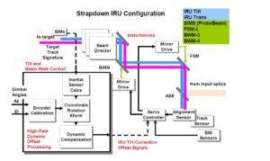
Two quite distinct alternative configurations, the stable-platform and the strapdown pointing and stabilization implementation architectures for large aperture space-to-space optical systems are described.
A necessary condition for selecting an inertial reference approach is that it meet jitter performance requirements. Jitter performance must be achieved in the prescribed base motion environment, that is, in the presence of platform base motion. The angular base motion is of obvious concern, though any significant disturbance must be evaluated. Linear motion may be an issue because of the way it couples into angular motion of the system and the way it might couple as measurement errors in the sensors. If both strapdown and stabilized-platform approaches meet performance criteria and have comparable costs, then the less-complex system is preferred. Often the less complex system has lower cost, but the complexity factor is included to capture the additional work required for integrating, checking out, testing, and maintaining the more complex approach.
In many applications, both the strapdown and stabilized-platform approaches are technically viable mechanizations for LOS stabilization. The choice of mechanization depends primarily on the pointing accuracies required and the magnitudes of the base motion angular vibration that exists in the system. Generally, it is argued that the simpler implementation makes the strapdown mechanization the superior approach provided that this approach can meet the overall performance goals. In some applications, however, the desired performance cannot be achieved with the strapdown approach, because the sensors cannot accommodate the large bandwidth and large dynamic range of the underlying disturbance base motion. These applications can be handled only by the stabilized-platform approach which gives superior performance to that attainable with strapdown mechanizations.
The stabilized platform approach entails a two-axis tip-tilt platform with integrally mounted inertial angle sensors and an alignment probe beam. The alignment probe beam is propagated through the optical train to an alignment sensor that detects the angular misalignment
of the probe beam with respect to an alignment fiducial reference. The sensor error signals drive an alignment servo control loop to null the sensor-alignment error. The platform is articulated (a few milliradians travel, maximum) relative to its gimbal mounted base with push-pull voice-coil actuators. For terrestrial applications, the stabilized IRU is assumed to be mounted on a multiaxis gimbal to provide large-angle field-of-regard coverage. Tracker measurements of the target pointing error, or inertial angle commands, control the stable platform to point it toward the target. The platform angles with respect to its base are then used to point the host platform as a follower control system.
Stabilized inertial reference platform beam control architecture. This configuration is explicit for the case in which the beam director telescope is gimbaled with respect to a host platform.
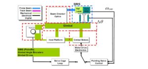
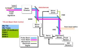
This configuration is explicit for the case in which the beam director telescope is gimbaled with respect to a host platform. The configuration diagram for an optical alignment loop needed to null the beam path errors is depicted in Figure below. The optical path shows dual-mirror actuators. A fast steering mirror (FSM) controls jitter, while a beam walk mirror (BWM) controls beam translation. Beam jitter and beam walk alignment sensors control these mirror actuators in a feedback servo control fashion.
Beam train optical path alignment control loop. The optical path shows dual mirror actuators. A fast steering mirror controls jitter, while a beam walk mirror controls beam translation. Beam jitter and beam walk alignment sensors control these mirror actuators in a feedback servo control fashion.
In the strapdown approach, the inertial sensors are hard mounted to the beam expander telescope directly adjacent to an alignment reference. The angular motion of the reference surface is measured, and a correction signal is applied to the alignment loop to correct the error. Often this correction is done only in a high-pass (no DC) context, because of the errors inherent in measuring and correcting DC bias error with inertial only systems. The key elements of a strapdown stabilization approach are an alignment system, including reference beam, beam sensor, and a reference surface indicative of the telescope output optical axis. Also, there is an inertial sensor measurement of the reference surface motion.
Strapdown stabilization beam control architecture. This configuration is explicit for the case in which the inertial angle sensors are strapped to the telescope. The gyro measured angular rate (or delta inertial angle) is used in an attitude computation to implement a telescope rate stabilization control loop.
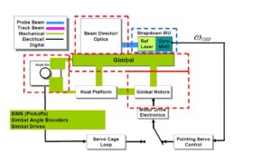
High-rate offset processing required for the strapdown implementation. The alignment system includes jitter alignment and beam walk sensors, just as it does for the stabilized platform mechanization. High-rate data processing is required to implement the calibration, and coordinate rotation and dynamic compensation computations for implementing the alignment system pointing offset. These angle offsets correct telescope pointing error.
Gimbal Systems Design Considerations for Small UAS
Regarding sUAS gimbal systems design, while Miller et al. did a wide comparison between different configurations to provide a broad overview of the design concepts. According to Miller et al., the first aspect of gimbal system design is to decide the number of gimbal axes needed for a desired LoS control and field-of-regard (FoR), which is the area over which the gimbal can point. A minimum of two axes are required for controlling two degrees of freedom and point the LoS in a two-dimensional (vertical/tilt/pitch and horizontal/pan/yaw) desired direction. To control a third degree of freedom, such as the image orientation, a third axis is needed. In small sUAS, two-axis gimbal systems are most commonly used. In fixed-wing sUAS, it is common to use gimbal systems with an outer azimuth gimbal axis to control the pan so that it is able to rotate 360 degrees and therefore have a wider FoR. Another important design aspect is to correctly align the center of gravity with the gimbal motors. By doing this, the required torque and power to make precise angular rotations can be greatly reduced. Thermal considerations must also be addressed because sUAS gimbal systems are commonly too small to package cooling fans or heat exchangers. Therefore, correct electronics layout and proper materials selection are the best measures to mitigate thermal problems
Drive System
The gimbal drive system can be direct, where the motor controls the axis directly, or indirect, via cables, gears or belts. Gimbals with brushless DC direct drive have the highest performance, being able to achieve very low friction and no reflected inertia. However, it is usually heavier, bigger and more expensive than the other approaches to achieve the same torque, and needs more complex electronics. If an indirect drive with gears or belts is chosen, the solution is cheaper and smaller, but has increased backlash, hysteresis, cogging and compliance as result. The cable drive approach has a performance between the direct drive and gears/belts approaches but it has higher friction and lower stiffness, and difficulty achieving 360 degree continuous motion for the yaw axis. The commercial brushless gimbal systems are often supplied with a dedicated controller which uses input from an IMU to be mounted on the camera.
Alignment Actuators
Once an angular error in the beam train has been sensed, it needs to be corrected. Steering mirrors are typically used for this application. Often these are designated Fast Steering Mirrors (FSMs) to distinguish them from low-bandwidth steerable mirrors used for static
alignment applications. FSMs typically have tip-tilt control and are driven by push-pull actuator pairs. Often they have position sensors indicating the off-null angular position of the mirror. The alignment actuators requirements are also identical in both stabilized platform and
strapdown beam control configuration. The gimbal and beam optical path errors, relative to the target LOS, are the same in both cases. Hence, the actuators required to null these error should have the same control dynamic range and bandwidth requirements to achieve the same overall alignment performance.
Platform
A mechanical platform serves as the mounting assembly for the inertial instruments and the optical probe beam. This mechanical assembly holds the inertial instruments and the IRU probe beam in alignment with respect to each other. The platform is articulated in two axes (tiptilt) using high-bandwidth voice-coil actuators. These actuators operate in push-pull pairs to impart a torque on the platform in reaction to the base. The torque angularly accelerates the platform, and is used to control inertial angular rate and, hence, the inertial attitude [i.e. the
pointing direction / line-of-sight ( LOS)]. Precision linear pickoff sensors, operated differentially, measure the relative displacement of the platform, with respect to the base, on opposite ends of a diameter passing through the platform flex pivot. These differential linear sensors give an output proportional to the angle of the platform with respect to the base. A precision flex pivot allows the platform high compliance (low stiffness) motion in 2 degrees-offreedom (tip-tilt) while providing low compliance in the other degrees-of-freedom.
Sensor Type and Location
There are 4 basic types of angular rate sensors available for use in LOS stabilization systems: mechanical rate gyros, Coriolis rate sensors, Fiber Optic Gyros (FOGs), and Ring Laser Gyros (RLGs). They are listed in order of current performance capability. While RLG based
gyros exhibit the highest performance levels they suffer from a periodic loss of rate data availability during internal frequency changes that make them difficult to use for LOS stabilization applications (they would need a back-up rate sensor).
Within each type the performance levels vary dramatically. The main figure of merit for rate sensors is the drift rate stability (measured in º/hour over the operating temperature range). The difference between low and high performance rate sensors used in LOS stabilization systems can vary by several orders of magnitude. High drift rates require regular mulling with “drift pots”. These rate sensors can be single axis devices or combined with accelerometers into a 3-axis Inertial Measurement Unit (IMU).
Individual sensors can be mounted directly on each gimbal axis or mounted at right angles to each other on the LOS. Integrated IMUs are
mounted directly to the LOS. Mounting the sensors directly on the LOS yields the highest bandwidth but requires the measured rates to be
resolved back to each of the actuators axes. This complicates the control software.
HEL-JTO Advanced Beam control for Locating and Engaging (ABLE) program
Background: The HEL-JTO is chartered to advance the state of the art in High Energy Laser (HEL) technology with a focus on complimenting existing service HEL System demonstrations as well as looking ahead to Beam Control requirements for the next generation
HEL systems. In the next 10 years or more, a number of tactical HEL missions will require the ability to image and track targets in deep turbulence and precisely point and compensate the wavefront of an outgoing HEL beam.
The HEL-JTO Advanced Beam control for Locating and Engaging (ABLE) program is actively pursuing adaptive optics and tracking technologies for demonstrating improved beam control effectiveness under severe atmospheric and aero-optics turbulence conditions expected for Service platform scenarios. However, these solutions in their current state are complicated systems that will require significant SWaP reductions prior to deployment onboard weapon platforms.
Examples of past HEL- JTO efforts to reduce beam control SWaP and improve performance include: Digital holography imaging and wavefront sensing, Stochastic Parallel Gradient Descent (SPGD), passive wavefront sensing, Digital Focal Plane Array (DFPA), Light Weight
Beam Director (LWBD), and Active Primary Deformable Mirror (APDM). HEL-JTO is actively pursuing adaptive optics technology via the Advanced Beam Control Demonstration project as a part of the ABLE program to address moderate turbulence levels, with Rytov levels between 0.5 and 1.0. The next generation beam control systems will require operating in Rytov levels >1.0.
Objective: New techniques are sought for the correction and control of high-average-power and/or high-peak-power (pulsed) laser propagation through the atmospheric boundary layer, low altitude atmosphere, aero-optic flows, and other environments with strong turbulence (Rytov > 1.0).
Proposals could include analysis, 3-D modeling, simulation (including adaptive optics and advanced control algorithms), component development and experiments.
Impact: The successful development of methods for propagating high energy lasers through deep turbulence could drastically improve the effectiveness of high energy laser systems for the warfighter. It could enable missions and platforms previously thought to be precluded
from high energy lasers.
Multi-Axis Precision Seeker-Laser Pointing Gimbal
The technology within this topic is restricted under the International Traffic in Arms Regulation (ITAR), 22 CFR Parts 120-130, which controls the export and import of defense-related material and services, including export of sensitive technical data, or the Export Administration Regulation (EAR), 15 CFR Parts 730-774, which controls dual use items. Offerors must disclose any proposed use of foreign nationals (FNs), their country(ies) of origin, the type of visa or work permit possessed, and the statement of work (SOW) tasks intended for accomplishment by the FN(s) in accordance with section 5.4.c.(8) of the solicitation and within the AF Component-specific instructions. Offerors are advised foreign nationals proposed to perform on this topic may be restricted due to the technical data under US Export Control Laws. Please direct questions to the AF SBIR/STTR Contracting Officer, Ms. Gail Nyikon, gail.nyikon@us.af.mil.
OBJECTIVE: Develop a line-of-sight stabilized miniature gimbal for a nose-mount application in a small weapon/unmanned air vehicle (UAV) that can precisely point a laser rangefinder, laser jammer or designator beam via Coude’ Path across all three gimbal axes.
DESCRIPTION: The technologies associated with small weapons and small Intelligence, Surveillance, and Reconnaissance (ISR) UAVs and miniaturization of laser radars and laser target markers/designators has progressed rapidly. However, the higher powered versions of these lasers are generally too large to be packaged as a payload component in the small multi-axis gimbals on loitering weapons or small UAVs. This is especially true when considering that the stabilized payload generally contains one or more imaging systems, laser rangefinders, or other components and has severe thermal constraints.
In order to minimize aerodynamic drag and to provide the required field of regard (FOR), the use of a nose-mounted, three-axis gimbal is been determined to be the preferred configuration(roll, pitch, yaw) with a “fourth” or half axis referring to beam stabilization. In this configuration the outer gimbal axis would be aligned with the roll axis of the UAV; the middle gimbal axis would be elevation, with the inner axis being cross-elevation.
This would facilitate a required FOR relative to the air vehicle of at least +30 degree / -135 degree elevation, ± 135 azimuth (larger desired). For the particular class of vehicles, the maximum outside diameter of the gimbal would be about five and one-half inches. To enable laser marking/designation capability from a laser that is too large to fit within the payload, but able to be packaged within a 5-inch cylinder, the beam must be projected through the gimbal crossing all three axes via Coude’ Path. Packaging the laser outside the inner gimbal also facilitates a better thermal management solution which is a critical element for extended operation of these small weapon applications.
The types of lasers used in these applications typically have a center wavelength between 1 and 1.5 micrometer, beam diameters of approximately 4 millimeters, beam divergences of approximately one-half milliradian with pulsed energies in excess of 50 millijoules (mJ) (1/2 megawatt to megawatt peak). Masking of the airframe and wings must be accomplished based on gimbal angle and airspace management for eye-safety of aircrews.
A multifocal or zoom optics approach is desirable but recognized to have performance challenges. Thus, the optical elements used to steer the laser beam must be able to withstand these energy densities, and must be kept free of debris and contaminants and environmental issues (condensation) that would degrade performance. The challenges associated with providing the precise alignments to route the laser path through the gimbal, and providing the electrical power and digital signal paths up to1.5 Gb/s for each video stream across the axes in the tight package is formidable.
In conjunction with these packaging challenges, the payload must be stabilized to less than 100 µrad RMS jitter. This stabilization performance must be achieved on UAVs with operating speeds of 100 KTS (weapons with speeds up to 300 KTS), and angular motion rates in excess of 100 degrees per second in gusty environments, in addition to high frequency vibration from the motor and propeller. As in all small platforms weight, power, and cost are critical elements of consideration for endurance, cost, and platform performance (drag, center of gravity, etc.).
The objective is to incorporate an optical and sensor payload with the 1064 nm or other lasers to acquire, track, and illuminate a specific point on the target at slant ranges over 3 kilometers. The optical payload must acquire and precisely track the target and resolve under 0.5 meter aim-point on moving targets day or night.
The target tracker must hold the laser spot aim-point on a particular point of a target, once operator designated, regardless of target motion, change of orientation, and in the presence of background contrast changes and clutter. The tracker must be predictive so that target transition behind and through structures and trees or clouds will adjust anticipated re-acquire point and open search window to identify target by “memory” of characteristics for scenarios with many movers. Closed loop spot position imaging and management with in band sensors target acquisition with IR and other imaging sensors is envisioned.
System weight of 5 pounds for the larger gimbals and 2 pounds for the small gimbal are design goals, and 80 G launch loads, with 8 to 10 G peak to peak -100 Hz vibration from reciprocating engine propulsion. Air speeds for operation range from 40knots to 250knots with altitudes from sea level to greater than 20,000 feet AGL. Temperature ranges in carriage can exceed -40 degrees C to 70 degrees C.
PHASE I: Design a 3+ axis gimbal concept that can steer a high-energy pulsed or CW laser beam & stabilize it with an on-payload imaging systems to less than 100 µrad RMS jitter for small weapons and UAS environments. Show ability to achieve the stabilization & steer the payload & laser over the required FOR, within a diameter of 3 to 5 inches. Demonstrate critical components in lab/field demonstrations.
PHASE II: Carry the concept from Phase I into a form-fit-function prototype. Design, build, integrate and test the prototype with a suitable laser to demonstrate conformance to requirements. Through hardware in the loop and tower/ surrogate flight testing on SUAS or other fixed wing platforms show the pointing and tracking capability to maintain track on moving targets is sufficient to hold the laser spot on the designated point.
PHASE III DUAL USE APPLICATIONS: Transition into numerous DoD applications and use for laser point to point communications, astronomical, and police applications requiring helicopter and small aircraft precision tracking.