 International Defense Security & Technology Your trusted Source for News, Research and Analysis
Related Articles

Optical communications make use of light waves, very high frequency (100 terahertz) electromagnetic waves, for information transmission. Modern optical communications were begun in the 1960s, when lasers were invented as a coherent light source. Since then, the rapid development of photonic technologies has made possible optical communication links with a capacity of terabits per second and a transmission distance of many thousands of kilometers.
The explosive growth of optical communication technology in the past decades has revolutionized the telecom industry and created a global communication infrastructure with optical networks. Optical communication links and networks are essential for the Internet backbone as well as for interconnects used in data centres and high-performance computing systems. The increasing demand for fiber optic solutions is driven by the need for high bandwidth communication, alongside the growing awareness of the benefits of adopting fiber optic technology.
Fiber optic communications provide many benefits. Resistance to Electromagnetic Interference: in practical cable deployment, it’s inevitable to meet environments like power substations, heating, ventilating and other industrial sources of interference. However, fiber has a very low rate of bit error (10 EXP-13), as a result of fiber being so resistant to electromagnetic interference. Fiber optic transmission is virtually noise free.
Low Security Risk: the growth of the fiber optic communication market is mainly driven by increasing awareness about data security concerns and use of the alternative raw material. Data or signals are transmitted via light in fiber optic transmission. Therefore there is no way to detect the data being transmitted by “listening in” to the electromagnetic energy “leaking” through the cable, which ensures the absolute security of information.
One of the areas where there is an increased need for fiber optics and circular fiber connectors is military applications. Fiber optics can be found in everything, from tactical military communication systems to terrain vehicles. For instance, some applications for which fibre optic products can provide unrivalled security and stability include shipboard communications, ship to shore communications, and deployable tactical communications. The increased speed of data transmissions allowed by fibre optic products, for example, can be a very major factor contributing to their use for military purposes. When every second counts, and every piece of data is invaluable, it’s necessary to use the product which provides the highest and most consistent level of performance and when it comes to data transmission, that level can only be provided by fibre optic.
Fiber Optic Transmission Technology
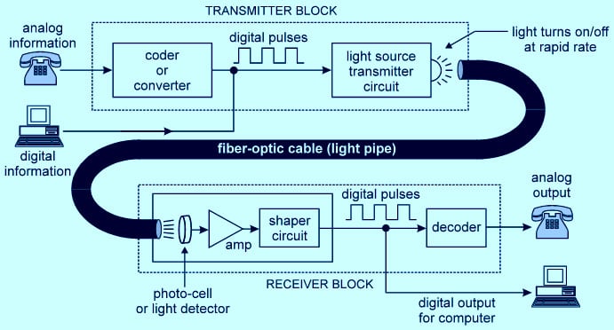
Usually, a fiber optic communication system consists of three main components: optical transmitter, fiber optic cable and an optical receiver. The optical transmitter converts information-carrying electronic signal to optical signal; the fiber optic cable carries the optical signal from the optical transmitter to the optical receiver; and the optical receiver reconverts the optical signal to an electronic signal so that the information is recovered and delivered to the destination. The most commonly used optical transmitter is semiconductor devices like LEDs (light-emitting diodes) and laser diodes. Photodetector is the key part of an optical receiver. It converts light into electricity using photodetector effect.
As for the fiber optic cable, there is too much to say. As the use and demand for speed and bandwidth, the development of optical cables is amazing. Now in the optical cable market, there are OS2 fIber , OM1 fIber, OM2 fIber, OM3 fIber, OM4 fiber and OM5 fiber cable for different optical applications. Optical fibers are used as a medium for telecommunication and networking because it is flexible and can be bundled as cables. It is especially advantageous for long-distance communications, because light propagates through the fiber with little attenuation compared to electrical copper cables.
Optical Fibers
The main driver of optical communication networks is advancement on optical fibers and optical components. An optical signal consists of a series of pulses produced by switching a laser beam off and on. Its speed depends on how fast the beam can be switched on and off, and how much the pulses spread in length during transmission, an effect called dispersion. The amount of dispersion depends on the type of fiber, the fiber length and the nature of the optical signal. The more dispersion, the more difficult it is to distinguish between adjacent pulses. With current technology, different types of fiber can be combined to reduce dispersion effects, allowing transmission at 10 gigabits per second for a few thousand kilometers. To achieve faster transmission speeds, researchers are exploring ways to actively compensate for dispersion.
Optical systems with advent the laser and optical fiber advances are driving optical communications, which support unlimited bandwidth and very low losses for long distance. Companies are racing to introduce new fiber technologies to enahance the speed to terrabit / sec and petabits/sec. CableLabs President and CEO Phil McKinney, conducting interviews at CES 2018, says the path forward to boost fiber capacity is by borrowing techniques from long-haul networks and getting rid of unnecessary overhead to increase speed. Coherent optics utilizes the ability to transmit multiple bits of information using light, including amplitude and phase modulation, instead of a simple binary on-off approach. Adding QPSK and QAM, plus polarization means you can move a lot more data onto a single strand of fiber.
Fiber cable types
An optical fiber cable consists of a core, cladding, and a buffer (a protective outer coating), in which the cladding guides the light along the core by using the method of total internal reflection. The core and the cladding (which has a lower-refractive-index) are usually made of high-quality silica glass, although they can both be made of plastic as well. Connecting two optical fibers is done by fusion splicing or mechanical splicing and requires special skills and interconnection technology due to the microscopic precision required to align the fiber cores.
Two main types of optical fiber used in optic communications include multi-mode optical fibers and single-mode optical fibers. A multi-mode optical fiber has a larger core (≥ 50 micrometers), allowing less precise, cheaper transmitters and receivers to connect to it as well as cheaper connectors. However, a multi-mode fiber introduces multimode distortion, which often limits the bandwidth and length of the link. Furthermore, because of its higher dopant content, multi-mode fibers are usually expensive and exhibit higher attenuation. The core of a single-mode fiber is smaller (<10 micrometers) and requires more expensive components and interconnection methods, but allows much longer, higher-performance links. Both single- and multi-mode fiber is offered in different grades.
In order to package fiber into a commercially viable product, it typically is protectively coated by using ultraviolet (UV), light-cured acrylate polymers, then terminated with optical fiber connectors, and finally assembled into a cable. After that, it can be laid in the ground and then run through the walls of a building and deployed aerially in a manner similar to copper cables. These fibers require less maintenance than common twisted pair wires once they are deployed.
Specialized cables are used for long distance subsea data transmission, e.g. transatlantic communications cable. New (2011–2013) cables operated by commercial enterprises (Emerald Atlantis, Hibernia Atlantic) typically have four strands of fiber and cross the Atlantic (NYC-London) in 60–70ms. Cost of each such cable was about $300M in 2011.
Another common practice is to bundle many fiber optic strands within long-distance power transmission cable. This exploits power transmission rights of way effectively, ensures a power company can own and control the fiber required to monitor its own devices and lines, is effectively immune to tampering, and simplifies the deployment of smart grid technology.
Dispersion
For modern glass optical fiber, the maximum transmission distance is limited not by direct material absorption but by several types of dispersion, or spreading of optical pulses as they travel along the fiber. Dispersion in optical fibers is caused by a variety of factors. Intermodal dispersion, caused by the different axial speeds of different transverse modes, limits the performance of multi-mode fiber. Because single-mode fiber supports only one transverse mode, intermodal dispersion is eliminated.
In single-mode fiber performance is primarily limited by chromatic dispersion (also called group velocity dispersion), which occurs because the index of the glass varies slightly depending on the wavelength of the light, and light from real optical transmitters necessarily has nonzero spectral width (due to modulation). Polarization mode dispersion, another source of limitation, occurs because although the single-mode fiber can sustain only one transverse mode, it can carry this mode with two different polarizations, and slight imperfections or distortions in a fiber can alter the propagation velocities for the two polarizations. This phenomenon is called fiber birefringence and can be counteracted by polarization-maintaining optical fiber. Dispersion limits the bandwidth of the fiber because the spreading optical pulse limits the rate that pulses can follow one another on the fiber and still be distinguishable at the receiver.
Some dispersion, notably chromatic dispersion, can be removed by a ‘dispersion compensator’. This works by using a specially prepared length of fiber that has the opposite dispersion to that induced by the transmission fiber, and this sharpens the pulse so that it can be correctly decoded by the electronics
Lasers
The Bit rate-Distance (BL) has increased to meet the requirements of high-speed communication networks, where B is the bit rate and L is the repeater spacing. The first generation of lightwave systems employed lasers operating near 0.8 microns and used a multi-mode fibers for a bit rate of 45 Mbps, with repeater spacings of up to 10 km.
Then, lasers working at wavelength of 1.3 microns were used in the second generation of optical networks, and the data rates transmitted through single-mode fiber were up to 1.7 Gbps for 50 Km of a repeater spacing. Afterwards, developments were obtained a single longitudinal mode laser and very low losses of optical fiber. The third generation commercially operated at 1.55 microns with single longitudinal modes where the bit rates achieved up to 10 Gbps, and the distance between electronic repeaters was limited to 60-70 km.
One of the properties of lasers is the reduced spectral distribution of their optical emission as compared to other light sources. However, this laser ‘linewidth’ can be greatly influenced by the environmental conditions, which deteriorate their performance when used outside the research lab. This issue is known to be one of the limitations in the deployment of coherent higher-order modulation transceivers for emerging applications; for instance, 5G wireless.
In Oct 2020, the Department of Engineering, Aarhus University, received a grant from the Independent Research Fund Denmark to investigate nonlinear effects in semiconductor lasers – a stepping-stone to enable next generation higher-order modulation in fibre optic networks. This project is based on a recent breakthrough discovery made by Assistant Professor Nicolas Volet and Dr. Holger Klein, Director of Chip Design at the US-based company OE Solutions America, Inc (OESA).
“We have discovered a method to effectively narrow the linewidth of a laser by a factor of up to 500, which is required to enable higher-order modulation formats in coherent communication, where information is encoded in the phase, amplitude and polarization of the lightwave signal. This unique approach can reduce the cost, size and power consumption compared to today’s laser technology,” says Dr. Holger Klein. Nicolas Volet continues: “Indeed, this discovery is extremely encouraging as it is expected to turn a notorious limitation of semiconductor lasers into an opportunity to increase optical network transport capacity and simplify their packaging for real-world applications. Our group will work closely with OESA’s Photonic Integrated Circuit (PIC) design team in Santa Barbara, CA led by Dr. Klein to study and further improve this new breakthrough technology.”
Receivers
The main component of an optical receiver is a photodetector which converts light into electricity using the photoelectric effect. The primary photodetectors for telecommunications are made from Indium gallium arsenide. The photodetector is typically a semiconductor-based photodiode. Several types of photodiodes include p-n photodiodes, p-i-n photodiodes, and avalanche photodiodes. Metal-semiconductor-metal (MSM) photodetectors are also used due to their suitability for circuit integration in regenerators and wavelength-division multiplexers.
Optical-electrical converters are typically coupled with a transimpedance amplifier and a limiting amplifier to produce a digital signal in the electrical domain from the incoming optical signal, which may be attenuated and distorted while passing through the channel. Further signal processing such as clock recovery from data (CDR) performed by a phase-locked loop may also be applied before the data is passed on.
Coherent receivers use a local oscillator laser in combination with a pair of hybrid couplers and four photodetectors per polarization, followed by high speed ADCs and digital signal processing to recover data modulated with QPSK, QAM, or OFDM.
Nanostructure Allows Large Incidence Angles in Fiber Optics, reported in Nov 2020
Researchers from ITMO, in collaboration with the Leibniz Institute of Photonic Technology and Australian National University, have resolved the fundamental problem of light coupling into optical fiber at incidence angles of over 70°. The researchers used a dielectric nanostructure with a high refractive index, made from silicon nitride, implemented at the end face of the optical fiber, to overcome the fact that in conventional optical fibers at a incidence angle of 15°, efficiency drops to nearly zero. The drop significantly limits the functionality and potential of optical fiber-based applications.
Due to the diffractive properties of the ringed nanostructure, light passed through the structure in such a way that it propagated exactly along the optical fiber axis, even under a large incidence angle. The structure’s ringed shape made it possible to capture light of any polarization and incident from nearly any direction. With this design, light in-coupling efficiency increased by four orders compared with traditional optical fibers or those with a metal nanostructure.
“I think we succeeded due to the harmonic combination of specialists in the fields of optical fibers and optical nanostructures, and teamwork between theoreticians and experimenters,” said Oleh Yermakov, a Ph.D. graduate of the Department of Physics and Engineering at ITMO. “We advanced from a superficial understanding of the problem to a detailed concept, analytical description, and a precise numerical model. This helped us come up with the optimal structure design, which was then fabricated and measured by our German colleagues.” The researchers plan to speed up, simplify, and reduce the cost of nanostructure fabrication through the use of nanoimprint lithography. For now, the researchers are transforming their theoretical advances into an algorithm to find nanostructures for any particular task through machine learning.
Precision laser coupling device for single-mode fiber optics, reported in Sep 2020
In Sep 2020 it was reported that U.S. Air Force scientist Matthew Squires has invented a positioning device for the stable and repeated coupling of a laser beam and a fiber optic cable. The device contains four prisms (two Risley prism pairs) that can change the laser beam’s angle of incidence and position. The prisms are precisely manipulated by an electric motor, which is directed by a computerized controller connected to an optical sensor that provides feedback on the beam coupling. The controller’s software allows the device to effectively mitigate or eliminate hysteresis.
Optical frequency combs
At a systemic level, the researchers also demonstrated the advantages of using ‘optical frequency combs’ instead of having separate laser transmitters for each frequency channel. An optical frequency comb emits light at all wavelengths simultaneously, making the transmitter very frequency-stable. This makes reception of the signals much easier – and thus more energy efficient.
Manufacturing Fiber Optic Glass Under Pressure reported in Dec 2020
Silica glass for fiber optics applications may perform better when manufactured under high pressure, according to research from Penn State and AGC Inc. in Japan. Researchers demonstrated that doing so reduced signal loss in the material.
John C. Mauro, professor of materials science and engineering at Penn State, and his team used molecular simulations to evaluate the use of pressure when building optical fibers, showing that pressure quenching could reduce Rayleigh scattering loss by more than 50%. Rayleigh scattering occurs due to fluctuations in the glass’s atomic structure.

The voids (yellow) in silica glass become much smaller when the glass is quenched at higher pressures. Courtesy of Yongjian Yang, Penn State.
“Glass, on an atomic scale, is heterogeneous,” Mauro said. “It has an open porosity on an atomic scale that occurs randomly.” With pressure treatment of the glass, the homogeneity of the material would increase, and the number of microscopic holes in the structure would decrease, creating a higher mean density and less variability. “We were looking for the independent processes that can control mean and variance,” Mauro said. “We realized that the pressure dimension had not been explored previously.”
In theory, Mauro and his team proved that pressure could improve the glass quality; Madoka Ono of AGC Inc.’s Materials Integration Laboratories and a professor in the Research Institute for Electronic Science at Hokkaido University, put the theory into practice. The results matched the simulation.
“The optimum pressure we found was 4 gigapascals,” Mauro said. “But there is still a process challenge that needs to be addressed.” The glass must be formed and cooled under pressure while it is still in the glass transition phase, which is the point at which glass is not quite a solid and not quite a liquid. To achieve this, the researchers would need a pressure chamber capable of 40,000 atmospheres. “It’s possible, but we’re not quite there yet. We can get about halfway there with a macroscopically sized sample,” Mauro said.
References and Resources also include:
https://www.photonics.com/Articles/Manufacturing_Fiber_Optic_Glass_Under_Pressure/a66534