International Defense Security & Technology Your trusted Source for News, Research and Analysis
The function of the propulsion system is to produce thrust, which is the force that moves a rocket through air and space. Different propulsion systems generate thrust in different ways, but always through some application of Newton’s third law of motion. In any propulsion system, a working fluid is accelerated and the reaction to this acceleration produces a force on the system. A general derivation of the thrust equation shows that the amount of thrust generated depends on the mass flow through the engine and the exit velocity of the gas. The propulsion system of a rocket includes all the parts that make up the rocket engine: tanks, pumps, propellants, power head, and rocket nozzles.
Solid rocket motors (SRMs) are a critical technology for space and defense missions. These motors offer a high level of performance and reliability, making them ideal for applications where failure is not an option. In this article, we will explore the critical role that SRMs play in powering space and defense missions.
What are Solid Rocket Motors?
Solid rocket motors are a type of rocket motor that uses solid propellant to generate thrust. The propellant is stored in a solid form and is burned in a combustion chamber to produce hot gases that generate thrust. Solid rocket motors are often used in applications where a high level of reliability is required, such as military and space missions.
In a solid rocket fuel grain, all the components required for vigorous combustion are mixed together and packed into a solid cylinder, into one substance. Once the combustion starts, it proceeds until all the propellant is exhausted. There will be an oxidizer (usually a salt such as ammonium perchlorate or potassium nitrate), a fuel (HTPB – Hydroxyl Terminated Polybutadiene) or some other solid hydrocarbon and an accelerant (sulphur, powdered aluminium, or other easily oxidized metal). When lit, the fuel grain will burn energetically, releasing a large volume of hot gases that are used to provide thrust.
For deeper understanding on Solid Rocket Motors and Applications please visit: Solid Rocket Motors: From Concept to Launch, Science, Applications, Safety, and Future Trends
The Advantages of Solid Rocket Motors
Solid rockets inherently have fewer working parts, which typically relates to lower risks and costs. The storage life of solid propulsion systems is also greater than that of liquid systems, in that they do not require regular maintenance.
Solid rocket motors offer several advantages over other types of rocket motors, including:
- High thrust-to-weight ratio: Solid rocket motors have a high thrust-to-weight ratio, which means they can generate a large amount of thrust with a relatively small amount of weight.
- Simplicity: Solid rocket motors are simple in design, which makes them easier to manufacture and more reliable.
- Long storage life: Solid rocket motors have a long storage life and can be stored for many years without the need for maintenance.
- Insensitivity to shock and vibration: Solid rocket motors are less sensitive to shock and vibration than other types of rocket motors, which makes them ideal for military applications.
Disadvantages of SRMs
The disadvantage of standard solid propulsion has been the inability to be “throttled”, thus the initiative to enhance controllable solid rocket propulsion technologies. Some of disadvantages to using SRMs, including:
- Limited thrust control: SRMs have limited thrust control, which means that they cannot be throttled or shut down as easily as liquid rocket engines. This can be a problem for some applications, such as in-space maneuvering.
- Short burn time: SRMs have a short burn time, which means that they are not suitable for applications that require long periods of thrust, such as orbital insertion.
- Hazardous: SRMs can be hazardous to handle and transport, due to the high pressures and temperatures involved. This requires special procedures and equipment to ensure safety.
The Role of Solid Rocket Motors in Space Missions
Solid rocket motors play a critical role in space missions. They are used to launch spacecraft into orbit and to provide the thrust needed for course corrections and other maneuvers during the mission. Solid rocket motors are also used to boost spacecraft out of Earth’s orbit and to send them on missions to other planets.
One of the most notable uses of solid rocket motors in space missions is the Space Shuttle program. The Space Shuttle used two solid rocket boosters (SRBs) to provide the thrust needed to launch the spacecraft into orbit. The SRBs were the largest solid rocket motors ever flown and were capable of generating a combined thrust of 6.6 million pounds.
The Role of Solid Rocket Motors in Defense Missions
Solid rocket motors are critical to space and defense missions because of their long shelf life and ability to be launched with little preparation. They are used in a variety of applications, including missile systems and air defense systems. Solid rocket engines are used on air-to-air and air-to-ground missiles, on model rockets, and as boosters for satellite launchers.
One notable use of solid rocket motors in defense missions is the Trident II missile system. The Trident II uses three solid rocket motors to provide the thrust needed to launch the missile from a submarine. The solid rocket motors are highly reliable and are capable of delivering the missile to its target with a high degree of accuracy.
Because of the way they are built, these motors provide fast ignition and heavy-lift propulsion with reliable, repeatable results. Without the most cutting-edge technology in place to support these efforts, producing our solid rocket motors would add significant additional testing and expense.
“Going from rocket motor concept to full-scale production is rarely a straight path, but solving the myriad puzzles along the way always makes the process rewarding,” said Mike Fuller, manager at Northrop Grumman. According to Fuller, a solid rocket motor at its core is a relatively simple device with no moving parts. It includes an outer cylindrical casing, solid propellant with a hole — often star-shaped — down the center, called “the grain”, an igniter to light the propellant and a nozzle to exhaust the combustion gases.
“We mix fuel and oxidizer in liquid form, then cast it inside the composite or steel casing,” he said. “The igniter is essentially a mini-rocket motor whose flame ignites the inner surface of the propellant. The gas created by this combustion exits the casing through the nozzle, creating the thrust that drives the rocket forward.”
Principle
In a solid rocket, the fuel and oxidizer are mixed together into a solid propellant which is packed into a solid cylinder. A hole through the cylinder serves as a combustion chamber. When the mixture is ignited, combustion takes place on the surface of the propellant. A flame front is generated which burns into the mixture. The combustion produces great amounts of exhaust gas at high temperature and pressure. The amount of exhaust gas that is produced depends on the area of the flame front and engine designers use a variety of hole shapes to control the change in thrust for a particular engine. The hot exhaust gas is passed through a nozzle which accelerates the flow. Thrust is then produced according to Newton’s third law of motion.
The amount of thrust produced by the rocket depends on the design of the nozzle. The smallest cross-sectional area of the nozzle is called the throat of the nozzle. The hot exhaust flow is choked at the throat, which means that the Mach number is equal to 1.0 in the throat and the mass flow rate m dot is determined by the throat area. The area ratio from the throat to the exit Ae sets the exit velocity Ve and the exit pressure pe.
The exit pressure is only equal to free stream pressure at some design condition. We must, therefore, use the longer version of the generalized thrust equation to describe the thrust of the system. If the free stream pressure is given by p0, the thrust F equation becomes:
F = m dot * Ve + (pe – p0) * Ae
Notice that there is no free stream mass times free stream velocity term in the thrust equation because no external air is brought on board. Since the oxidizer is mixed into the propellant, solid rockets can generate thrust in a vacuum where there is no other source of oxygen. That’s why a rocket will work in space, where there is no surrounding air, and a gas turbine or propeller will not work. Turbine engines and propellers rely on the atmosphere to provide the oxygen for combustion and as the working fluid in the generation of thrust.
The thrust equation given above works for both liquid and solid rocket engines. There is also an efficiency parameter called the specific impulse which works for both types of rockets and greatly simplifies the performance analysis for rocket engines
Construction
A simple solid rocket motor consists of a casing, nozzle, grain (propellant charge), and igniter. Modern designs may also include a steerable nozzle for guidance, avionics, recovery hardware (parachutes), self-destruct mechanisms, APUs, controllable tactical motors, controllable divert and attitude control motors, and thermal management materials.
Payload, Drogue Chute, Payload/Avionics, Main Chute, Motor and Casing
Casing: The casing may be constructed from a range of materials.
Motor Case Materials: Composite ( E-glass, Aramid (Kevlar 49), Carbon fiber ), Metal ( Titanium alloy, Alloy steel, Aluminum alloy 2024 ), and combination
Titanium alloy: Heavy, Good strength to weight ratio
Alloy steel: Heavier, Strongest
Aluminum: Provides good strength to weight ratio, Lightest
Nozzles
A convergent-divergent design accelerates the exhaust gas out of the nozzle to produce thrust. The nozzle must be constructed from a material that can withstand the heat of the combustion gas flow. Often, heat-resistant carbon-based materials are used, such as amorphous graphite or carbon-carbon.
There are five types: Fixed (a), Movable (b), Submerged (c), Extendible (d) and Blast-Tube-Mounted (e)
The nozzle dimensions are calculated to maintain a design chamber pressure, while producing thrust from the exhaust gases.
Nozzles: Design and Construction
● Ablatively Cooled
● Steel or aluminum Shells
● Composite ablative liners
Aerotech L2200G-P Mojave Green and RMS 75/5120 kit comes with a nozzle
Igniters: Pyrogens and Pyrotechnic
Most frequent is Electroexplosive device (Pyrotechnic): Bridgewire
Propellant
A typical, well-designed ammonium perchlorate composite propellant (APCP) first-stage motor may have a vacuum specific impulse (Isp) as high as 285.6 seconds (2.801 km/s). Upper stage specific impulses are somewhat greater: as much as 303.8 s (2.979 km/s) for APCP (Orbus 6E)
Higher performing solid rocket propellants are used in large strategic missiles (as opposed to commercial launch vehicles). HMX, C4H8N4(NO2)4, a nitramine with greater energy than ammonium perchlorate, was used in the propellant of the Peacekeeper ICBM and is the main ingredient in NEPE-75 propellant used in the Trident II D-5 Fleet Ballistic Missile
Propellant Combustion
o Burn rate
o Flame Pattern
o Ignition Characteristics
Propellant Stability
o Acoustic Resonance
o Ignition Wire Configurations
o Internal Gas Flow Cavity Considerations
Conceptual design
Most solid rocket motors originate from new mission requirements. The SRM design is a highly integrated, highly iterative process that comprises the designing of several subsystems, namely, combustion chamber, nozzle, propellant grain, and insulation.
“We usually start off with a performance spec — deliver X amount of mass to a certain range — then design the rocket around it,” remarked Fuller. “Customers usually provide the initial requirements, but then we might suggest ways to improve the motor’s performance or reduce its cost.” These initial calculations drive the rocket motor’s conceptual design.
Engineering the Model Rocket
After the conceptual design is established, the rocket motor development team moves on to the detailed design of the motor’s major components, calculating, for example, the exact dimensions of its case, the composition of its propellant, the shape of the propellant grain and the critical performance characteristics of its nozzle.
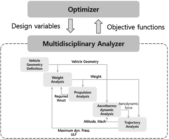
Designing a missile or a launch-vehicle system is a complex process that demands the integration of different engineering disciplines, for example, aerodynamics, propulsion, flight dynamics and trajectory, structure and mass/weight analysis, guidance and control, etc. Typically, each discipline is mathematically modeled, and its interactions with other disciplines are taken into account. A combination of two models (propulsion/aerodynamics) is common in missile design systems, although a combination of three models (propulsion/aerodynamics/flight dynamics) also exists in the literature
The design begins with the total impulse required, which determines the fuel and oxidizer mass. Grain geometry and chemistry are then chosen to satisfy the required motor characteristics. The propellant type is usually selected as early as possible according to the desired performance of the SRM under consideration, and more often depending on the available manufacturing technology and the organization’s expertise.
The design process should be carried out in a logical sequence, that is, independent design parameters should be identified as the first step, and then dependent design parameters are evaluated accordingly. Parameters derived from the mission/vehicle analysis and propellant properties are usually considered as independent design parameters. Mission analysis and vehicle definition define the ballistic performance required by the motor (average thrust, burning time, and total impulse), and provide the geometrical limits and operation conditions that constraint the design (motor length, weight, maximum expected operating pressure, temperature range, and ambient pressure
Practically, proper adjustment of design parameters always requires a balanced tradeoff between competing design objectives (e.g., between cost and performance, between mass and safety, etc.). For that reason, engineers and designers started early to use optimization techniques to perform the SRM design process effectively and efficiently. The optimum SRM design is the one that satisfies an optimum total impulse, an optimum thrust–time profile, an optimum nozzle configuration, an optimum chamber pressure, and a preferred solid-propellant-grain configuration.
The ballistic performance parameters can be summed into the thrust time profile, which provides a comprehensive measure for the overall SRM performance.
On the other hand, cost is always an essential factor in developing any rocket-based vehicle. The total vehicle mass (inert mass plus propellant mass) has traditionally been viewed as a primary driver toward the final vehicle cost. Therefore, minimizing the gross lift-off mass/weight was the main objective in many vehicle optimization studies.
Although SRMs are relatively simple in principle, their modern types are complex systems that must incorporate several technical disciplines and teams to meet stringent mission requirements and design criteria. To accomplish their objective within given overall system requirements and constraints, SRM subsystems and components must be carefully designed and optimized.
Extensive research has been conducted for decades to find the optimal design for a rocket vehicle that achieves the conflicting objectives of safety, reliability, performance, operability, and cost
“Every solid rocket motor design is a balancing act among performance, cost and complexity,” Fuller said. “We look for that sweet spot between casing material, propellant types and nozzle design to give the customer the performance they’re looking for at a cost that’s acceptable in a package we can produce.”
At the heart of this design process is computer simulation, Fuller emphasized. This allows the team to build, modify and virtually test an electronic model of the solid rocket motor under multiple potential operational scenarios.
“Every solid rocket motor design is a balancing act among performance, cost and complexity.” “We end up with a high-fidelity engineering model of the solid rocket motor that describes the physical characteristics of all of its individual components,” he said. “It lays out, in effect, how we plan to build that motor.”
Testing Subsystems
Before assembling the first article of the motor, the team tests each of its major components against a performance standard required for that part.
Common modes of failure in solid rocket motors include fracture of the grain, failure of case bonding, and air pockets in the grain. All of these produce an instantaneous increase in burn surface area and a corresponding increase in exhaust gas production rate and pressure, which may rupture the casing.
Another failure mode is casing seal failure. Seals are required in casings that have to be opened to load the grain. Once a seal fails, hot gas will erode the escape path and result in failure. This was the cause of the Space Shuttle Challenger disaster.
“We make most of our rocket motor cases at a Northrop Grumman manufacturing facility in Clearfield, Utah,” said Fuller. “Sometimes, we’ll pressurize a case to verify it can withstand its design limits — or even pressurize it until it fails, just to make sure it can withstand its expected operating environment.”
The team also mixes the proposed propellant in small, sub-scale quantities to ensure it mixes properly, tests it to make sure it burns properly, then scales it up to a production-sized mix, he added.
For a rocket motor’s igniter, Fuller explained that the design team often adapts a previously produced, previously characterized igniter to the current application. And regardless of whether the team makes or buys the rocket motor’s nozzle, they always conduct a separate test of the vector control system that moves the nozzle during flight.
Manufacturing
The first step in the process after a solid rocket motor case is wound together to form a composite case is to determine its dry mass by weighing it before any propellant is added. Afterward, the propellant — a very viscous product at this stage — is poured into the casing and allowed to cure until hardened. A small amount, 1 pound, is kept from each batch. This is called a 1-pound charge and is a very critical part of the data used to design the flight profile for each solid motor upper stage.
“Of these mixes of propellant, a little bit of it is put to the side, called a 1-pound charge, and then we take that into a test facility, and we burn it, and we measure the energy output from the burn,” said Kurt Eberly, Director Space Launch Programs, Northrop Grumman.
Here, the precisely calibrated estimate of the total energy of the stage can be determined when combined with a second weighing of the motor case after the propellant is cured and machined to its proper shape. The difference between the dry mass and fueled mass gives the precise mass of the propellant… which coupled with the measurement of the burn energy of the 1-pound charge provides the detailed estimate for the total energy in the stage.
“So then our propulsion system group puts that all into a ballistics report for us, all these weights and energy that we’re going to get, and so on, and then they send that to us over at Launch Vehicles. And then we take that ballistics report and we do our own modeling,” added Kurt.
Mike Ruth then continued, “So we take that data and a ballistics file — and that’s basically the main data set for what the predicted or nominal history vs time of the engine thrust vs. the remaining propellant mass.”
Takeoff
The real proof of a solid rocket motor design comes during a static test of the fully assembled motor. According to Fuller, Propulsion Systems tests its rocket motors in Promontory, and preparations for a test can vary from a few days to several months depending on the requirements, the customer and the program.
“During rocket motor testing, we strap the motor onto a test stand, put it up against a block that can withstand the force of the rocket, wire it up with measuring equipment, then fire the motor to see if it does what we think it’s going to do,” he said.
Fuller added that the key measurement tool for this test is called a thrust trace. This is a data plot of the amount of thrust produced versus time over the duration of the burn. By analyzing the thrust trace, the test team can determine if the propellant is burning evenly.
The test team also uses high-speed video to analyze the visual characteristics of the nozzle and exhaust during rocket motor testing, he added. And a post-test examination of key components helps to determine whether those components responded as expected to propellant burning at 6,000 degrees Fahrenheit.
The Future of Solid Rocket Motors
Solid rocket motors are likely to continue playing a critical role in space and defense missions for many years to come. However, there are also ongoing efforts to develop new technologies that could improve the performance and reliability of these motors. For example, researchers are exploring new types of solid propellant that could offer better performance and lower costs.
Conclusion
SRMs are versatile and reliable technology that has been used in a variety of space and defense missions. They offer a number of advantages, including simplicity, reliability, and low cost. However, they also have some disadvantages, such as limited thrust control and short burn time.
Solid rocket motors are a critical technology for space and defense missions. They offer a high level of performance and reliability and are ideal for applications where failure is not an option. As the space and defense industries continue to evolve, we can expect to see ongoing advancements in solid rocket motor technology that will further improve their performance and reliability.