International Defense Security & Technology Your trusted Source for News, Research and Analysis
Related Articles
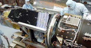
The space vehicles greatly vary in size from small satellites and CubeSats to vehicles such as the Mars Rover and other large launch vehicles. All of these spacecraft have electronic devices that need to operate properly in space with a very low failure rate.
Modern computers operate in a “noisy” electronic environment. They are surrounded by powerful electromagnetic interference (EMI) generated by radios, radar, microwave transmitters, other computers, and a wide assortment of electronic equipment. Electromagnetic Interference (EMI) is electromagnetic energy that disturbs, interrupts, obscures or degrades the effective performance of the electrical equipment.
Electromagnetic Compatibility (EMC) is a condition that prevails when various electrical devices are performing their functions accordingly to the intended design in its common electromagnetic environment. Electromagnetic compatibility (EMC) is the ability of electrical equipment and systems to function acceptably in their electromagnetic environment, by limiting the unintentional generation, propagation and reception of electromagnetic energy which may cause unwanted effects such as electromagnetic interference (EMI) or even physical damage in operational equipment.
EMC standards establish verification requirements to control the characteristics of EMI emission and susceptibility levels on electrical and electromechanical equipment and its subsystems. Generally, EMC standards provide fundamental conditions and limits on how the product must perform, all while specifying test procedures depending on the device’s product family and general use with consideration to its environment when in operation. EMC standards can be commonly divided along the following industries: commercial, automotive, aerospace, medical and military.
Space vehicles EMC requirments
Just about all of the data collected by NASA Mars Rovers return to Earth through a relay link from the Mars surface to a Mars Reconnaissance Orbiter circling Mars. All of this science data comes from omnidirectional antennas for simplicity. However, this system is quite susceptible to RF interference coming from nearby science payloads and spacecraft subsystems, which downgrades link performance by a factor of 2+.
Most of the interference generates from Fourier overtones via switching power supplies, data lines, stepper motors, and clocks. This EMI on the spacecraft is pretty stable in frequency; however, the EMI tones’ complements will vary as the spacecraft operating mode changes.
The two primary mechanisms responsible for charging are plasma bombardment and photoelectric effects. Hot electrons roaming the outer radiation belt can pelt the satellite, causing a negative charge to build on its surface — a charging event. Discharges as high as 20,000 V have been known to occur on satellites in geosynchronous orbits. If protective design measures are not taken, electrostatic discharge, a buildup of energy from the space environment, can damage the devices.
When ESD happens, stored charges are released. These create a discharge current that may generate conducted emissions, which happen when a replacement current originating as a charge is blown off a dielectric surface. This induces a replacement current flowing from a satellite or spacecraft structure. Radiated emissions are generated by the ESD current pulse. When a rapid surface potential changes, the effect is noise-induced in circuitry via capacitive coupling. Also, discharge currents can inductively induce a signal into a victim circuit. These inductive, capacitive, and field-to-circuit couplings are manifestations of transient radiated and conducted EMI.
NASA also published “Analysis of Radiated EMI from ESD events caused by Space Charging.” This effort used modeling to analyze conducted and radiated EMI caused by electrostatic discharge (ESD) events in space. NASA engineers looked at surface charging, which could develop on the exterior of satellite surfaces, due to the interaction between those surfaces and the space plasma environment. NASA’s extensive research assessed charging mechanisms present when dielectric surfaces of any spacecraft become exposed to the space plasma environment, usually at geosynchronous Earth orbit (GEO) and POLAR orbits.
EMI / EMC for satellites
The effects from Electromagnetic Interference (EMI) can be considered destructive to vital electrical subsystems regarding space missions. When a spacecraft experiences anomalies, it is important to distinguish whether it occurred due to a command transmitted from the Ground Station or by interference on the spacecraft. The anomalies from the environment can be caused by radiation and the RF environment. There are multiple cases of operational failures or malfunctions on spacecraft. Be it EMI coming from spacecraft charging from the natural space plasma or electromagnetic energy transferring from one device to another.
Human life, of course, must be protected against any catastrophic failures that may be caused by EMI as the prime objective. The secondary objective is to protect the very expensive space vehicles against failures due to EMI radiation from electronics within these vehicles, as well as any possible EMI from spacecraft docking with other spacecraft.
High levels of contamination on surfaces can contribute to electrostatic discharge. Satellites are vulnerable to charging and discharging. For that reason, space applications require components with no floating metal. Satellite charging is a variation in the electrostatic potential of a satellite, with respect to the surrounding low-density plasma around the satellite. The extent of the charging depends on the design of the satellite and the orbit.
The hazards caused by spacecraft charging are varied,” said Dr. Joseph Minow, NASA Technical Fellow for Space Environments. If a charge builds up that is too big for the spacecraft’s material to hold, discharge arcs, which are essentially strong electrical currents, will occur. And depending on where those arcs go, they can damage electronic components, destroy sensors, or damage important materials such as thermal control coatings. “They can also show up in electrical systems as phantom commands,” he said. The arcs can spoof the attitude control system, for example, causing attitude changes or spin anomalies. The arcs also emit electromagnetic radiation and cause interference and noise that can hamper both incoming and outgoing command and control as well as science data signals.
Dr. Minow said, “The best solution to mitigating charging hazards is good design. Just turning off the sensitive systems to avoid geomagnetic storms isn’t practical for most satellites. Good material selection is important. If we build satellites for geostationary orbit with conductive coatings on the outside, the arc will go out into space. Differential charging is the worst because arcs originating in one location on a spacecraft can damage systems on another part of the spacecraft. Fortunately, design techniques to minimize the amount of differential charging are well understood.”
Along with good design is testing, particularly in environments that expose the spacecraft components to arcing. And more design and testing is being done with computer modeling, he notes. “We can simulate the charge build up and variations in voltage across the vehicle. We can see the motion of the particles. A combination of both analytical work and testing yields the best satellite design,” he said.
Modern gridded ion thrusters for CubeSats operate by generating high power and can pose challenging problems with Electromagnetic Interference (EMI). The system is comprised of a thruster, a Power Processing Unit (PPU), a propellant storage tank, a feed system, and passive thermal management. The thrust is generated by accelerating ions across a set of biased grids, creating an ion beam that is charged and current neutralised by an external thermionic cathode. The system’s input voltage can be set between 12 V and 28 V and the bus interface can be either Controller Area Network (CAN) or I2C.
Standards
Verifying that spaceflight systems are electromagnetically compatible is one of the necessary precautions to ensure a successful mission. Spacecraft equipment is considered by National Aeronautics and Space Administration (NASA) to fall under the military industry (GSFC-STD-7000A, 2013) (MILSTD-461G, 2015).
Not only the Aerospace system vehicles, even their interfaces such as space vehicle interfaces, launch vehicle interfaces, launch site interfaces, payload interfaces, ground support equipment interfaces, test equipment interfaces, and ordnance interfaces must meet all these EMC requirements
When EMC methods are implemented early on in the development process, there are more pre-emptive mitigation options with less costs in time and money. Mitigation method examples commonly involve better shielding and grounding methods, and placement planning when integrating the spacecraft. By performing in-house pre-compliance tests and taking measures to prepare for the tests at a certified EMC test house, the company can be more confident in their product at passing the EMC tests.
Typically, radiated emission requirements are specified for satellite equipment that is intended to be turned on during launch, to avoid interference within the frequency bands designated for the launcher (ECSS-E-ST-20-07C, 2012). For other cases, the ECSS standard specifies that radiated emissions at low frequency field are measured only for characterisation and the obtained results are used to verify compliance with system level requirements.
Anechoic chamber
Anechoic chambers are used today for performing EMC measurements according to a variety of published EMC standards. There are many different fields of application, including consumer electronics, automotive, aerospace, military, medical, telecommunications and others.
An RF anechoic chamber is a room where the electromagnetic waves are completely absorbed by the walls, giving the effect of an infinitely large room where the measured waves originate only directly from the source which eliminates noise from reflections or external sources. The RF anechoic chamber is similar to an acoustic anechoic chamber, but the difference lies in the material and geometry of the wall covers, i.e. the RF anechoic chamber’s interior surface is covered with radiation absorbent material. Radiative emission and susceptibility tests are performed in these chambers to avoid spurious signals and reflections from the setup disrupting the accuracy of the measurement.
EMC anechoic chambers, especially those with conductive floors (called semi-anechoic chambers or SAC), are primarily used for testing radiated emissions (RE) in the frequency range from 30 to 1000 MHz and radiated immunity (RI) from 26 or 80 MHz to 1000 MHz, with extensions to 6 GHz, 18 GHz, or even 40 GHz with RE measurements becoming more frequent. While there are standards that call for radiated measurements down to the low kHz or even to the low Hz range, these standards do not specify any need for absorption or anechoic behavior as the chamber validation criterion starts at 30 or 80 MHz. In most cases, at these low frequencies where current absorber technology cannot deliver any level of absorption, the chambers are going to be too small (electrically) for resonant modes to appear.
Microwave Pyramidal Absorber
The name may be misleading as this material is used down to 200 MHz or even 80 MHz, well below the traditional microwave range. This material is generally referred to as the traditional “blue stuff” or “blue foam.” This is a material where a substrate (usually polyurethane) is loaded with carbon. To achieve any level of absorption, the material must be of a certain electrical size from the base to the tip of the pyramid. Thus, it is commonly used at higher frequencies. There are, however, some chambers used for EMC where this material is still used. The original EMC chambers in the early 1980s used this material with pyramids having 2.4m in length in order to have usable undesired reflection suppression down to 30 MHz.
More recently, multi-purpose chambers such as the Satellite-Antenna-EMC-Measurement chamber at the Laboratory of Integration and Testing (LIT) of the INPE (Brazilian National Institute of Space Research) used specially cut 1.8m pyramids to meet the EMC requirements as well as the absorption levels for antenna measurements over the frequency range of 500 MHz to 40 GHz.
References and Resources also include:
https://interferencetechnology.com/choosing-the-right-chamber-for-your-test-requirements/