International Defense Security & Technology Your trusted Source for News, Research and Analysis
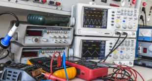
Modern computers operate in a “noisy” electronic environment. They are surrounded by powerful electromagnetic interference (EMI) generated by radios, radar, microwave transmitters, other computers, and a wide assortment of electronic equipment. Electromagnetic Interference (EMI) is electromagnetic energy that disturbs, interrupts, obscures or degrades the effective performance of the electrical equipment. Electromagnetic Compatibility (EMC) is a condition that prevails when various electrical devices are performing their functions accordingly to the intended design in its common electromagnetic environment.
EMC standards establish verification requirements to control the characteristics of EMI emission and susceptibility levels on electrical and electromechanical equipment and its subsystems. Generally, EMC standards provide fundamental conditions and limits on how the product must perform, all while specifying test procedures depending on the device’s product family and general use with consideration to its environment when in operation. EMC standards can be commonly divided along the following industries: commercial, automotive, aerospace, medical and military.
Aerospace and defense applications such as fighter jets and attack helicopters require that electronic systems meet stringent MIL-STD-461 and RTCA DO-160 requirements for electromagnetic interference (EMI), electromagnetic compatibility (EMC), and other environmental conditions. NASA has defined vehicles as airborne and space-borne assemblages of units and subsystems which will operate together to provide payload support functions and to launch space assets.
MIL-STD-461, currently MIL-STD-461G, is an electromagnetic compatibility testing standard published and maintained by the United States Department of Defense (U.S. DoD). Its official title is Requirements for the Control of Electromagnetic Interference Characteristics of Subsystems and Equipment. MIL-STD-461 is used as is by many countries around the world and has been adapted and is the basis for many other EMI specifications by countries throughout the world.
Space vehicles requirements
The space vehicles greatly vary in size from small satellites and CubeSats to vehicles such as the Mars Rover and other large launch vehicles. All of these spacecraft have electronic devices that need to operate properly in space with a very low failure rate.
Just about all of the data collected by NASA Mars Rovers returns to Earth through a relay link from the Mars surface to a Mars Reconnaissance Orbitercircling Mars. All of this science data comes from omnidirectional antennas for simplicity. However, this system is quite susceptible to RF interference coming from nearby science payloads and spacecraft subsystems, which downgrades link performance by a factor of 2+.
Most of the interference generates from Fourier overtones via switching power supplies, data lines, stepper motors, and clocks. This EMI on the spacecraft is pretty stable in frequency; however, the EMI tones’ complements will vary as the spacecraft operating mode changes.
Human life, of course, must be protected against any catastrophic failures that may be caused by EMI as the prime objective. The secondary objective is to protect the very expensive space vehicles against failures due to EMI radiation from electronics within these vehicles, as well as any possible EMI from spacecraft docking with other spacecraft.
Not only the Aerospace system vehicles, even their interfaces such as space vehicle interfaces, launch vehicle interfaces, launch site interfaces, payload interfaces, ground support equipment interfaces, test equipment interfaces, and ordnance interfaces must meet all these EMC requirements
NASA also published “Analysis of Radiated EMI from ESD events caused by Space Charging.” This effort used modeling to analyze conducted and radiated EMI caused by electrostatic discharge (ESD) events in space. NASA engineers looked at surface charging, which could develop on the exterior of satellite surfaces, due to the interaction between those surfaces and the space plasma environment. NASA’s extensive research assessed charging mechanisms present when dielectric surfaces of any spacecraft become exposed to the space plasma environment, usually at geosynchronous Earth orbit (GEO) and POLAR orbits.
When ESD happens, stored charges are released. These create a discharge current that may generate conducted emissions, which happen when a replacement current originating as a charge is blown off a dielectric surface. This induces a replacement current flowing from a satellite or spacecraft structure.
Radiated emissions are generated by the ESD current pulse. When a rapid surface potential changes, the effect is noise induced in circuitry via capacitive coupling. Also, discharge currents can inductively induce a signal into a victim circuit. These inductive, capacitive, and field-to-circuit couplings are manifestations of transient radiated and conducted EMI.
Military Requirements for EMC
The DoD created an Electromagnetic Compatibility Program to address the growing concern that EMI was affecting military operations with the goal of integrating electromagnetic compatibility into defense industry R&D.
Electromagnetic compatibility (EMC) is the ability of electrical equipment and systems to function acceptably in their electromagnetic environment, by limiting the unintentional generation, propagation and reception of electromagnetic energy which may cause unwanted effects such as electromagnetic interference (EMI) or even physical damage in operational equipment. The goal of EMC is the correct operation of different equipment in a common electromagnetic environment.
MIL-STD-461G is the military test standard that establishes requirements for the electromagnetic compatibility (EMC) of devices and systems created for and used by the United States Department of Defense (DoD). MIL-STD-461 is a military standard that establishes electromagnetic interference (EMI) limits and test procedures for military equipment.
Keeping EMI under control is critical for military applications. It can cause interference with other equipment and be detected by the enemy. MIL-STD-461 is an important testing standard for the military. It ensures that the ruggedized computer systems they operate can function properly within electromagnetic (EM) environments and avoid releasing EM energy that could potentially cause EM interference (EMI) with nearby devices.
Space-constrained programs and applications that utilize numerous embedded computer systems are growing in number, and thus, the propensity for EMI between them is growing, too. Detecting rogue signals and electromagnetic interference is crucial to the military, as everything from a cellphone to a navigation component on a stealth jet produces an electromagnetic field and can potentially threaten safety, efficiency or secret communications.
Battlefield computers have to contend with an exceptional level of interference created by military-specific items, such as IED jammers. Of course, EMI protection has grown in importance with the adoption of net-centric warfare doctrine. Even worse, enemy forces may also hijack the electromagnetic spectrum and disrupt electrical and electronic systems being used by the U.S. military. This weaponization of the EM spectrum is known as electronic warfare.
MIL-STD-461 testing is important for safety and mission success. If a rugged server or workstation isn’t MIL-STD-461-compliant but is being used as part of a mission-critical system, there’s an increased likelihood of mission disruption, mission failure and even a total loss of data, all of which carry potentially disastrous consequences, especially when national security is at play.
EMI requirements vary widely from one application to another (jeeps vs. airplanes, for instance) and even within an application (above deck and below deck on a Navy ship). MIL-STD-461 is a set of requirements intended to serve a wide range of platforms from trucks to ships to aircraft to fixed installations, and many different applications (e.g., above deck and below deck on a Navy ship).
MIL-STD-461 vs. MIL-STD-464
MIL-STD-461 and MIL-STD-464 are sometimes confused because they both address electromagnetism and electromagnetic environments. The difference between MIL-STD-461 and MIL-STD-464, however, is quite simple. The former addresses specific pieces of equipment and subsystems, and the latter addresses systems and platforms at large.
“This standard is best suited for items that have the following features: electronic enclosures that are no larger than an equipment rack, electrical interconnections that are discrete wiring harnesses between enclosures, and electrical power input derived from prime power sources.” – Excerpt from MIL-STD-461
“This standard establishes electromagnetic environmental effects (E3) interface requirements and verification criteria for airborne, sea, space, and ground systems, including associated ordnance.” – Excerpt from MIL-STD-464. In short, MIL-STD-464 is a collection of baseline system- and platform-level requirements and verification methods for fully assembled systems – the submarine, the launch vehicle, the surface ship and the others mentioned in MIL-STD-461.
It’s helpful to think of MIL-STD-464 as the integrated system standard for electromagnetic compatibility. MIL-STD-461, on the other hand, dives into the specifics of EMC testing for the smaller equipment and subsystems. It also serves as a testing guide for compliance testing engineers. Furthermore, MIL-STD-464 addresses system life cycle stages as they relate to E3. These stages include normal operation, packaging, transportation, storage, among others.
MIL-STD-461
Qualifications of defense electronic sub-systems according to a standard are an important step in the military system development. US Department of Defence (DoD) standard series MIL-STD-461 is a widely accepted standard at sub-system level qualification. A MIL-STD-461 certification ensures that a system doesn’t suffer from EM interference or disrupt other devices near it.
EMC pursues three main classes of issues. Emission is the generation of electromagnetic energy, whether deliberate or accidental, by some source and its release into the environment. EMC studies the unwanted emissions and the countermeasures which may be taken in order to reduce unwanted emissions.
The second class, susceptibility, is the tendency of electrical equipment, referred to as the victim, to malfunction or break down in the presence of unwanted emissions, which are known as Radio frequency interference (RFI). Immunity is the opposite of susceptibility, being the ability of equipment to function correctly in the presence of RFI, with the discipline of “hardening” equipment being known equally as susceptibility or immunity. A third class studied is coupling, which is the mechanism by which emitted interference reaches the victim.
Interference mitigation and hence electromagnetic compatibility may be achieved by addressing any or all of these issues, i.e., quieting the sources of interference, inhibiting coupling paths and/or hardening the potential victims. In practice, many of the engineering techniques used, such as grounding and shielding, apply to all three issues.
The standard addresses emissions generated by equipment as well as the susceptibility of equipment to degraded operation in the presence of external emissions. Tests procedures and limits are defined for EMI transferred via conducted and radiated means. EMC testing requirements are based on the Environment(s) of Intended Use: e.g. Ground ( Vehicle Personnel & Buildings), Aircraft ( Airforce, Army, Navy), Shipboard( Army/Navy, Submarines) as well as the location of the equipment (e.g. above deck, below deck, flight-line, etc). While the standard suggests these limits, it advises that the levels be adjusted to ensure the best integration of all the equipment.
Since its initial publication in 1967, MIL-STD-461 has undergone a total of seven revisions: MIL-STD-461A (1968); MIL-STD-461B (1980); MIL-STD-461C (1986); MIL-STD-461D (1993); MIL-STD-461E (1999); MIL-STD-461F (2007); MIL-STD-461G (2015)
MIL-STD-461 requirements
In the pages of MIL-STD-461G, a comprehensive set of test procedures are defined to fulfill the DoD’s electromagnetic emissions and susceptibility regulations. The test procedures are broken up into four groups: radiated emissions (RE), conducted emissions (CE), radiated susceptibility (RS) and conducted susceptibility (CS).
Each MIL-STD-461 requirement is identified by three-digit number succeeding a two-letter combination.
- Conducted emissions requirements are designated by CE
- Radiated emissions requirements are designated by RE
- Conducted susceptibility requirements are designated by CS
- Radiated susceptibility requirements are designated by RS
Procedures are named with one of the two-letter abbreviations followed by a code; for example, RE103, a radiation emissions test procedure specific to antenna spurious and harmonic outputs.
MIL-STD-461 Requirement Matrix
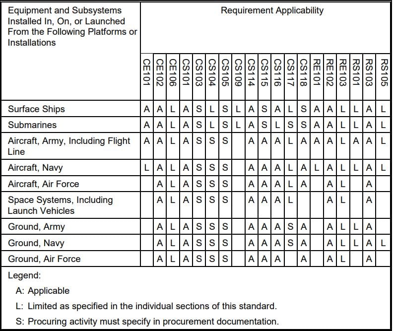
Conducted emissions refer to EM energy generated by a system or device and transmitted through its power cord via an electric current. Radiated emissions, on the other hand, refer to the unintentional generation of EM energy from a system or device. In turn, conducted susceptibility and radiated susceptibility refer to a device’s or system’s vulnerability to conducted and radiated emissions, respectively. These can also be referred to as conducted immunity and radiated immunity, which instead specify a system’s or device’s resistance to both types of emissions.
The ambient levels must be controlled to maintain the integrity of the measurement. When testing, it is specified on the necessity to measure ambient electromagnetic levels while the EUT is turned off and the auxiliary equipment turned on. As stated in the standard, the measured ambience must be 6 dB below the specified limit. The frequency range of defining the limits of the radiated emissions is across a wide bandwidth from 30 Hz to 40 GHz. The particular bandwidth for each test depends on the requirement or if specified otherwise, on the operating frequency range of the EUT.
Standard Setups
When conducting measurements, the placement and setup of all the equipment is important. The aim of the setup is to achieve repeatability when moving from one lab setup to another. The setup requirements vary within the standard depending on the size of the EUT, i.e. whether it is small enough to be placed on a table or the dimensions require the EUT to be placed next to the table while the chassis is still grounded to the ground plane.
Radiative emission and susceptibility tests are performed in RF anechoic chamber (the room where the electromagnetic waves are completely absorbed by the walls ) to avoid spurious signals and reflections from the setup disrupting the accuracy of the measurement.
An RF anechoic chamber is a room where the electromagnetic waves are completely absorbed by the walls, giving the effect of an infinitely large room where the measured waves originate only directly from the source which eliminates noise from reflections or external sources. The RF anechoic chamber is similar to an acoustic anechoic chamber, but the difference lies in the material and geometry of the wall covers, i.e. the RF anechoic chamber’s interior surface is covered with radiation absorbent material. Radiative emission and susceptibility tests are performed in these chambers to avoid spurious signals and reflections from the setup disrupting the accuracy of the measurement.
Reverberation chambers are used for measuring the effectiveness of shielding when performing radiated susceptibility tests, as the goal is to create with a transmitting antenna various modes for specific standing wave patterns in the chamber. Contrary to the anechoic chamber, the interior of the reverberating chamber is meant to reflect any signal, hence the requirement to construct everything from metallic material.
Line Impedance Stabilisation Network (LISN)
The LISN is an easy to use coupling and standard impedance device and has a wide application, and has been integrated into most of the commercial and military standards. In general, the LISN is required to provide a defined impedance control from the power source and ensure test repeatability. With defined impedance control, the EUT can be expected to have a proper supply of AC or DC.
Furthermore, the LISN isolates the experiment from the mains which is meant as electrical power from the wall outlet and the bench top power supply. The aim is to always measure noise originating only from the EUT. Thus, by connecting a LISN between the power source and experiment, any RF noise, such as the mains hum, originating from the supply does not affect the EUT nor the measurement.
The LISN has two ports meant as a feedthrough path for DC and a coaxial terminal for connecting to a measurement receiver. Conducted emission measurements are taken from the signal output port of the LISN. The readings give the magnitude of any RF noise reflected to the power lines of the experiment.
Conducted Emissions
CE101 and CE102 cover the conducted emissions related to the power leads including returns that are connected to a power source outside of the system being tested. These test procedures are used to verify that electromagnetic emissions from the equipment under test (EUT) do not exceed the specified requirements for power input leads including returns.
Conducted emissions imply that electromagnetic energy is created in an electronic device and is coupled to its power cord. The main reason of the conducted emission test is to verify that the conducted noise on the power cables of the EUT does not disturb the voltage distribution along the power bus on the whole platform. Therefore, the limits of the conducted emissions are measured in volts. If the system proves to be incompatible, i.e. emission levels are above the specified limit level, corrective actions are taken before the final system assembly.
For measuring the emissions coming from the EUT the setup requires an oscilloscope, a LISN, a signal generator for calibration and a ground plane. In addition, the EUT and LISNs are expected to be in a shielded enclosure. In the ECSS Standard, a current probe on the neutral line is used to measure emissions between the EUT and LISN. However, the military standard requires a voltage probe measuring from the output port of the LISN.
MIL-STD-461G CE102 ensures that EM emissions from the equipment being tested do not exceed the power lead and AC / DC limits outlined in Figure CE102-1 of MIL-STD-461. MIL-STD-461G CE102 is applicable to equipment installed on: Surface ships; Submarines Army, Navy and Air Force aircraft; Space systems, including launch vehicles; Army, Navy and Air Force ground platforms and installations
CE106 is conducted emissions related to the antennae terminal of transmitters, receivers, and amplifiers. The equipment under test should not exceed the specified limits. This test procedure is used to verify that conducted emissions appearing at the antenna terminal of the EUT do not exceed specified requirements.
Conducted susceptibility
This measurement verifies that the EUT performs without anomalies or degradation when the Direct Current (DC) power bus, antenna ports or even the chassis experience a disturbance such as a ripple. The ripple is generated by a signal which is injected to the respective input and the system’s reaction is recorded. Most of the tests use an inductive probe which couples the energy on to the EUT hardware. Compared to the previous versions of the MIL-STD-461, the most recent one features conducted susceptibility tests in case of lightning-induced transients
(CS117) and electrostatic discharge effects from personnel (CS118). Same concept susceptibility tests are defined in the ECSS standard as well.
CS101 is applicable to equipment and subsystem AC (limited to current draws ≤ 100 amperes per phase) and DC input power leads not including returns. The equipment under test (EUT) should not malfunction, degrade in performance, or deviate from specified indications, beyond the tolerances indicated in the individual equipment or subsystem specification, when subjected to a test levels. This test procedure is used to verify the ability of the EUT to withstand signals coupled onto input power leads.
CS103 and CS104 are for the receiver front-end susceptibility requirement applicable to equipment and subsystems, such as communications receivers, RF amplifiers, transceivers, radar receivers, acoustic receivers, and electronic warfare receivers as specified in the individual procurement specification. CS103 is conducted susceptibility for antenna port, intermodulation, 15 kHz to 10 GHz. The EUT shall not exhibit any intermodulation products beyond specified tolerances when subjected to the limit requirement provided in the individual procurement specification. This test procedure is used to determine the presence of intermodulation products that may be caused by undesired signals at the EUT antenna input terminals. CS104 is conducted susceptibility for antenna port, rejection of undesired signals, 30 Hz to 20 GHz. The EUT shall not exhibit any undesired response beyond specified tolerances when subjected to the limit requirement provided in the individual procurement specification. This test procedure is used to determine the presence of spurious responses that may be caused by undesired signals at the EUT antenna input terminals.
CS105 is the receiver front-end susceptibility requirement is applicable only to receivers that normally process amplitude-modulated RF signals, as specified in the individual procurement specification. The EUT shall not exhibit any undesired response, due to cross modulation, beyond specified tolerances when subjected to the limit requirement provided in the individual procurement specification. This test procedure is used to determine the presence of cross-modulation products that may be caused by undesired signals at the EUT antenna terminals.
CS106 is the requirement applicable to submarine and surface ship equipment and subsystem AC and DC input power leads, not including grounds and neutrals. The EUT shall not exhibit any malfunction, degradation of performance, or deviation from specified indications, beyond the tolerances indicated in the individual equipment or subsystem specification, when subjected to a test signal with specified voltage levels. This test procedure is used to verify the ability of the EUT to withstand transients coupled onto input power leads.
CS109 is for equipment and subsystems that have an operating frequency of 100 kHz or less and an operating sensitivity of 1 μV or better (such as 0.5 μV). Handheld equipment is exempt from this requirement. The EUT shall not exhibit any malfunction, degradation of performance, or deviation from specified indications, beyond the tolerances indicated in the individual equipment or subsystem specification, when subjected to the specified values. This test procedure is used to verify the ability of the EUT to withstand structure currents.
CS114 is applicable to all interconnecting cables, including power cables. The EUT shall not exhibit any malfunction, degradation of performance, or deviation from specified indications beyond the tolerances indicated in the individual equipment or subsystem specification, when subjected to an injection probe drive level which has been pre-calibrated to the appropriate current limit. The requirement is not applicable for coaxial cables to antenna ports of antenna-connected receivers except for surface ships and submarines. This test procedure is used to verify the ability of the EUT to withstand RF signals coupled onto EUT associated cabling.
CS115 is applicable to all aircraft, space, and ground system interconnecting cables, including power cables. The requirement is also applicable for surface ship and submarine subsystems and equipment when specified by the procuring activity. The EUT shall not exhibit any malfunction, degradation of performance, or deviation from specified indications, beyond the tolerances indicated in the individual equipment or subsystems specification, when subjected to a pre-calibrated signal having rise and fall times, pulse width, and amplitude as specified in the requirement. This test procedure is used to verify the ability of the EUT to withstand impulse signals coupled onto EUT associated cabling.
MIL-STD-461G CS116 tests the ability of equipment to endure damped sinusoidal transients coupled onto equipment cables and power leads. MIL-STD-461G CS116 is applicable to equipment installed on surface ships, military aircraft, space systems and launch vehicles and military ground platforms and installations. It is limited in applicability to submarines.
CS116 is applicable to all interconnecting cables, including power cables, and individual high side power leads. Power returns and neutrals need not be tested individually. For submarine applications, this requirement is applicable only to cables and leads that exit the pressure hull. The EUT shall not exhibit any malfunction, degradation of performance, or deviation from specified indications, beyond the tolerances indicated in the individual equipment or subsystem specification, when subjected to a signal having the waveform and maximum current as specified in the requirement. This test procedure is used to verify the ability of the EUT to withstand damped sinusoidal transients coupled onto EUT associated cables and power leads.
Radiated Emissions
Radiated emissions measure intentional and unintentional by-products that are radiated from the equipment to protect the on-board receivers and sensors or units sensitive to magnetic induction from unintentional transmitters.
Examples of intentional frequencies are expected radiations from the system clocks, oscillators, coupling paths, power switching or RF subsystems which may reveal even higher radiated emission levels. Moreover, at the proximity of slits on the chassis, more prominent discharges can be documented. Unintentional radiated emissions can be considered as by-products in the form of harmonics coming from digital signals such as the communication bus.
Typically, radiated emission requirements are specified for satellite equipment that is intended to be turned on during launch, to avoid interference within the frequency bands designated for the launcher (ECSS-E-ST-20-07C, 2012). For other cases, the ECSS standard specifies that radiated emissions at low frequency field are measured only for characterisation and the obtained results are used to verify compliance with system level requirements.
In case for the military standard, radiated emission requirements in the magnetic field for spacecrafts are not mandatory to be compliant with. However, similar to the ECSS standard, the emission levels depend on ensuring compliance with the whole system. For example, the magnetic field emission limits may depend on sensors on-board the spacecraft such as magnetometers, whereas near field electric field emission measurements can help prevent capacitive crosstalk between cables.
RE101 is applicable for radiated emissions from equipment and subsystem enclosures, including electrical cable interfaces. The requirement does not apply to radiation from antennas. For Navy aircraft, this requirement is applicable only for aircraft with an anti-submarine warfare (ASW) capability. This test procedure is used to verify that the magnetic field emissions from the EUT and its associated electrical interfaces do not exceed specified requirements.
RE102 is applicable for radiated emissions from equipment and subsystem enclosures, all interconnecting cables, and antennas designed to be permanently mounted to EUTs (receivers and transmitters in standby mode). The requirement does not apply at the transmitter fundamental frequencies and the necessary occupied bandwidth of the signal. The requirement is applicable at different frequency ranges for ground, surface ships, submarines, aircraft, and space. This test procedure is used to verify that electric field emissions from the EUT and its associated cabling do not exceed specified requirements.
RE103 may be used as an alternative for CE106 when testing transmitters with their intended antennas. This requirement is met if the emissions do not exceed the applicable RE102 limit. CE106 is the preferred requirement unless the equipment or subsystem design characteristics preclude its use. This test procedure is used to verify that radiated spurious and harmonic emissions from transmitters do not exceed the specified requirements.
Radiated Susceptibility
The aim of the requirement is to guarantee that in the likely case of electric or magnetic field emissions from the environment or neighboring subsystems, the EUT does not show anomalies or failures in its performance nor shows signs of degradation. The limits are taken from worst-case scenarios in electromagnetic field radiation from e.g. power transformers or antenna transmissions from the launch site or the spacecraft itself. Examples for testing the use case is when a sensor is located at the main beam or sidelobes of a transmitting antenna on the spacecraft, or when the shielding integrity of the whole assembly needs verification.
RS101 is applicable to equipment and subsystem enclosures, including electrical cable interfaces. The requirement is not applicable for electromagnetic coupling via antennas. For equipment intended to be installed on Navy aircraft, the requirement is applicable only to aircraft with ASW capability. For Army ground equipment, the requirement is applicable only to vehicles having a minesweeping or mine detection capability. For submarines, this requirement is applicable only to equipment and subsystems that have an operating frequency of 100 kHz or less and an operating sensitivity of 1 μV or better (such as 0.5 μV). The EUT shall not exhibit any malfunction, degradation of performance, or deviation from specified indications, beyond the tolerances indicated in the individual equipment or subsystem specification, when subjected to the magnetic fields shown in the requirement. This test procedure is used to verify the ability of the EUT to withstand radiated magnetic fields.
MIL-STD-461G RS103 assesses the ability of equipment and its cabling to withstand electric fields. MIL-STD-461G RS103 is applicable to equipment installed on surface ships, submarines, military aircraft, space systems and launch systems and military ground platforms and installations.
RS103 is applicable to equipment and subsystem enclosures and all interconnecting cables. The requirement is applicable at different frequencies depending on the application. The EUT shall not exhibit any malfunction, degradation of performance, or deviation from specified indications, beyond the tolerances indicated in the individual equipment or subsystem specification, when subjected to the radiated electric fields in the requirement. This test procedure is used to verify the ability of the EUT and associated cabling to withstand electric fields.
RS105 is applicable to equipment and subsystem enclosures when the equipment or subsystem is to be located external to a hardened (shielded) platform or facility. The requirement is applicable for equipment intended solely for use on non-metallic platforms when specified by the procuring activity. The requirement is applicable to Army aircraft for safety critical equipment and subsystems located in an external installation. The EUT shall not exhibit any malfunction, degradation of performance, or deviation from specified indications, beyond the tolerances indicated in the individual equipment or subsystem specification, when subjected to a test signal having the waveform and amplitude shown in the requirement. This test procedure is used to verify the ability of the EUT enclosure to withstand a transient electromagnetic field.
EMC control
The damaging effects of electromagnetic interference pose unacceptable risks in many areas of technology, and it is necessary to control such interference and reduce the risks to acceptable levels.
The control of electromagnetic interference (EMI) and assurance of EMC comprises a series of related disciplines:
- Characterising the threat.
- Setting standards for emission and susceptibility levels.
- Design for standards compliance.
- Testing for standards compliance.
- For a complex or novel piece of equipment, this may require the production of a dedicated EMC control plan summarizing the application of the above and specifying additional documents required.
Characterising the threat
Characterisation of the problem requires understanding of:
- The interference source and signal.
- The coupling path to the victim.
- The nature of the victim both electrically and in terms of the significance of malfunction.
- The risk posed by the threat is usually statistical in nature, so much of the work in threat characterisation and standards setting is based on reducing the probability of disruptive EMI to an acceptable level, rather than its assured elimination.
Coupling mechanisms
There are four basic coupling mechanisms: conductive, capacitive, magnetic or inductive, and radiative. Any coupling path can be broken down into one or more of these coupling mechanisms working together.
Conductive coupling occurs when the coupling path between the source and the receptor is formed by direct electrical contact with a conducting body, for example a transmission line, wire, cable, PCB trace or metal enclosure. Conducted noise is also characterised by the way it appears on different conductors: Common-mode coupling: noise appears in phase (in the same direction) on two conductors. Differential-mode coupling: noise appears out of phase (in opposite directions) on two conductors.
Inductive coupling occurs where the source and receiver are separated by a short distance (typically less than a wavelength). Strictly, “Inductive coupling” can be of two kinds, electrical induction and magnetic induction. It is common to refer to electrical induction as capacitive coupling, and to magnetic induction as inductive coupling.
Capacitive coupling occurs when a varying electrical field exists between two adjacent conductors typically less than a wavelength apart, inducing a change in voltage on the receiving conductor.
Inductive coupling or magnetic coupling occurs when a varying magnetic field exists between two parallel conductors typically less than a wavelength apart, inducing a change in voltage along the receiving conductor.
Radiative coupling or electromagnetic coupling occurs when source and victim are separated by a large distance, typically more than a wavelength. Source and victim act as radio antennas: the source emits or radiates an electromagnetic wave which propagates across the space in between and is picked up or received by the victim
EMC design
Electromagnetic noise is produced in the source due to rapid current and voltage changes, and spread via the coupling mechanisms described above. Breaking a coupling path is equally effective at either the start or the end of the path, therefore many aspects of good EMC design practice apply equally to potential emitters and to potential victims. A design which easily couples energy to the outside world will equally easily couple energy in and will be susceptible. A single improvement will often reduce both emissions and susceptibility.
Grounding and shielding
Grounding and shielding aim to reduce emissions or divert EMI away from the victim by providing an alternative, low-impedance path. Techniques include:
- Grounding or earthing schemes such as star earthing for audio equipment or ground planes for RF. The scheme must also satisfy safety regulations.
- Shielded cables, where the signal wires are surrounded by an outer conductive layer that is grounded at one or both ends.
- Shielded housings. A conductive metal housing will act as an interference shield. In order to access the interior, such a housing is typically made in sections (such as a box and lid); an RF gasket may be used at the joints to reduce the amount of interference that leaks through. RF gaskets come in various types. A plain metal gasket may be either braided wire or a flat strip slotted to create many springy “fingers”. Where a waterproof seal is required, a flexible elastomeric base may be impregnated with chopped metal fibers dispersed into the interior or long metal fibers covering the surface or both.
Other general measures
- Decoupling or filtering at critical points such as cable entries and high-speed switches, using RF chokes and/or RC elements. A line filter implements these measures between a device and a line.
- Transmission line techniques for cables and wiring, such as balanced differential signal and return paths, and impedance matching.
- Avoidance of antenna structures such as loops of circulating current, resonant mechanical structures, unbalanced cable impedances or poorly grounded shielding.
- Eliminating spurious rectifying junctions that can form between metal structures around and near transmitter installations. Such junctions in combination with unintentional antenna structures can radiate harmonics of the transmitter frequency.
Emissions suppression
Additional measures to reduce emissions include:
- Avoid unnecessary switching operations. Necessary switching should be done as slowly as is technically possible.
- Noisy circuits (with a lot of switching activity) should be physically separated from the rest of the design.
- High peaks can be avoided by using the spread spectrum method, in which different parts of the circuit emit at different frequencies.
- Harmonic wave filters.
- Design for operation at lower signal levels, reducing the energy available for emission.
Susceptibility hardening
Additional measures to reduce susceptibility include:
- Fuses, trip switches and circuit breakers.
- Transient absorbers.
- Design for operation at higher signal levels, reducing the relative noise level in comparison.
- Error-correction techniques in digital circuitry. These may be implemented in hardware, software or a combination of both.
- Differential signaling or other common-mode noise techniques for signal routing
EMC testing
Testing is required to confirm that a particular device meets the required standards. It divides broadly into emissions testing and susceptibility testing. Open-area test sites, or OATS, are the reference sites in most standards. They are especially useful for emissions testing of large equipment systems. However RF testing of a physical prototype is most often carried out indoors, in a specialised EMC test chamber. Types of chamber include anechoic, reverberation and the gigahertz transverse electromagnetic cell (GTEM cell).
Sometimes computational electromagnetics simulations are used to test virtual models.
Like all compliance testing, it is important that the test equipment, including the test chamber or site and any software used, be properly calibrated and maintained.
Typically, a given run of tests for a particular piece of equipment will require an EMC test plan and follow-up test report. The full test program may require the production of several such documents.
Emissions testing
Emissions are typically measured for radiated field strength and where appropriate for conducted emissions along cables and wiring. Inductive (magnetic) and capacitive (electric) field strengths are near-field effects, and are only important if the device under test (DUT) is designed for location close to other electrical equipment.
For conducted emissions, typical transducers include the LISN (line impedance stabilisation network) or AMN (artificial mains network) and the RF current clamp.
For radiated emission measurement, antennas are used as transducers. Typical antennas specified include dipole, biconical, log-periodic, double ridged guide and conical log-spiral designs. Radiated emissions must be measured in all directions around the DUT.
Specialized EMI test receivers or EMI analysers are used for EMC compliance testing. These incorporate bandwidths and detectors as specified by international EMC standards. An EMI receiver may be based on a spectrum analyser to measure the emission levels of the DUT across a wide band of frequencies (frequency domain), or on a tunable narrower-band device which is swept through the desired frequency range. EMI receivers along with specified transducers can often be used for both conducted and radiated emissions. Pre-selector filters may also be used to reduce the effect of strong out-of-band signals on the front-end of the receiver.
Some pulse emissions are more usefully characterized using an oscilloscope to capture the pulse waveform in the time domain.
Susceptibility testing
Radiated field susceptibility testing typically involves a high-powered source of RF or EM energy and a radiating antenna to direct the energy at the potential victim or device under test (DUT).
Conducted voltage and current susceptibility testing typically involves a high-powered signal generator, and a current clamp or other type of transformer to inject the test signal.
Transient or EMP signals are used to test the immunity of the DUT against powerline disturbances including surges, lightning strikes and switching noise. In motor vehicles, similar tests are performed on battery and signal lines. The transient pulse may be generated digitally and passed through a broadband pulse amplifier, or applied directly to the transducer from a specialised pulse generator.
Electrostatic discharge testing is typically performed with a piezo spark generator called an “ESD pistol”. Higher energy pulses, such as lightning or nuclear EMP simulations, can require a large current clamp or a large antenna which completely surrounds the DUT. Some antennas are so large that they are located outdoors, and care must be taken not to cause an EMP hazard to the surrounding environment.
References and Resources also include: