International Defense Security & Technology Your trusted Source for News, Research and Analysis
Related Articles

In the realm of digital communication, the TCP/IP model stands as a cornerstone for how data is transmitted, received, and understood across networks. From browsing the web to sending emails, the TCP/IP model governs the flow of information, ensuring that our digital interactions are seamless and reliable. This blog post explores the TCP/IP model, its layers, and the protocols that make it all possible.
Protocols are essentially the rulebooks for how computers and devices communicate across networks. They dictate the format and procedures for message exchange, ensuring that data sent from one device can be understood by another. Each device involved in the communication must adhere to these rules, enabling seamless information transfer.
Key Functions of Protocols:
Protocols play a crucial role in managing the complexities of network communication.
Protocols are the backbone of modern network communication, enabling seamless data exchange by standardizing the rules and processes governing interactions between devices. One of their critical functions is segmentation and reassembly, where large messages are broken into smaller packets for efficient transmission and later reassembled at the destination. Through encapsulation, protocols wrap data with headers and footers containing essential metadata like addressing and error-checking information, ensuring that the data is correctly identified and processed during transmission. Additionally, protocols manage connection control, facilitating the establishment, maintenance, and termination of connections to provide reliable communication channels between devices.
Another essential role of protocols is to guarantee data integrity and smooth communication. They ensure ordered delivery, maintaining the correct sequence of data packets even if they arrive out of order. Flow control mechanisms regulate data transmission rates between sender and receiver, preventing congestion and ensuring efficient resource utilization. Similarly, error control detects and corrects transmission errors, enhancing reliability. Protocols also handle routing and multiplexing, directing packets through optimal paths in the network while enabling multiple data streams to coexist on the same connection. Collectively, these functions make protocols indispensable for managing the complexities of modern networking.
Protocols are layered to handle different aspects of communication, with each layer serving a specific function. The protocol stack refers to this collection of protocols, where each layer communicates with the one above and below it.
In modern telecommunications, there’s a strong trend towards using IP (Internet Protocol) networks. Satellite networks, for instance, are increasingly adopting IP technologies, following the broader shift in the industry.
What is the TCP/IP Model?
The TCP/IP model, also known as the Internet Protocol Suite, is a conceptual framework used to standardize and facilitate communication between computers over a network. Developed in the 1970s by the United States Department of Defense, this model has become the universal language of networking, enabling devices around the world to communicate with one another.
The TCP/IP model consists of four layers, each responsible for specific aspects of the communication process:
- Application Layer
- Transport Layer
- Internet Layer
- Network Interface Layer
Let’s break down each layer and the key protocols associated with them.
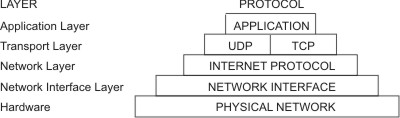
First, application programs send messages or streams of data to one of the Internet Transport Layer Protocols, either the User Datagram Protocol (UDP) or the Transmission Control Protocol (TCP). These protocols receive the data from the application, divide it into smaller pieces called packets, add a destination address, and then pass the packets along to the next protocol layer, the Internet Network layer. The Internet Network layer encloses the packet in an Internet Protocol (IP) datagram, puts in the datagram header and trailer, decides where to send the datagram (either directly to a destination or else to a gateway), and passes the datagram on to the Network Interface layer. The Network Interface layer accepts IP datagrams and transmits them as frames over a specific network hardware, such as Ethernet or Token-Ring networks.
1. Network Interface Layer: Physical and Data Link Layers
Function: The Network Interface Layer, also known as the Link Layer, is responsible for the physical transmission of data over the network medium, such as Ethernet cables or wireless signals. It deals with the hardware aspects of networking, including the transmission of raw data bits.
Physical Layer
The physical layer represents the physical devices that interconnect computers. The physical layer consists of devices and means of transmitting bits across computer networks. This includes the specifications for the networking cables and the connectors that join devices together along with specifications describing how signals are sent over these connections.
The physical layer includes the actual network devices and media (like cables) that transmit data as electrical or optical signals.
- Twisted Pair Cables: Common in Ethernet networks, these cables allow for duplex communication and come in various types, such as Cat 5e and Cat 6, which offer different speeds and resistance to interference. It’s called a twisted pair cable because it features pairs of copper wires that are twisted together. A standard cat six cable has eight wires consisting of four twisted pairs inside a single jacket. The most common forms of copper twisted-pair cables used in networking, are Cat 5, Cat 5e, and Cat 6 cables. Cat 5e cables have mostly replaced those older Cat 5 cables because their internals reduced crosstalk.Ethernet over twisted pair technologies are the communications protocols that determine how much data can be sent over a twisted pair cable, how quickly that data can be sent, and how long a network cable can be before the data quality begins to degrade. Cat 6 cables can transfer data faster and more reliably than Cat 5e cables can, but because of their internal arrangement, they have a shorter maximum distance when used at higher speeds.
Twisted pair network cables are terminated with a plug that takes the individual internal wires and exposes them. The most common plug is known as an RJ45, or Registered Jack 45. A network cable with an RJ45 plug can connect to an RJ45 network port. Network ports are generally directly attached to the devices that make up a computer network. Switches would have many network ports because their purpose is to connect many devices. But servers and desktops, usually only have one or two.
- Fiber Optic Cables: These offer higher speeds and longer transmission distances than copper cables but are more fragile and expensive. Fiber cables can transport data faster than copper cables can, but they’re much more expensive and fragile. Fiber can also transport data over much longer distances than copper can without suffering potential data loss, they are also immune to electromagnetic interference.
Data Link Layer
While the physical layer is all about cabling, connectors and sending signals, the data link layer is responsible for defining a common way of interpreting these signals, so network devices can communicate. Beyond specifying physical layer attributes, the Ethernet standards also define a protocol responsible for getting data to nodes on the same network or link. The data link layer manages communication between adjacent network nodes and handles error detection and correction.
Ethernet: The most common protocol at this layer, Ethernet uses MAC (Media Access Control) addresses to ensure data is sent to the correct device on a network. Ethernet uses MAC addresses to ensure that the data it sends has both an address for the machine that sent the transmission, as well as the one that the transmission was intended for. A MAC address is a globally unique identifier attached to an individual network interface. It’s a 48-bit number normally represented by six groupings of two hexadecimal numbers. Another way to reference each group of numbers in a MAC address is an octet. A MAC address is split into two sections. The first three octets of a MAC address are known as the organizationally unique identifier or OUI. These are assigned to individual hardware manufacturers by the IEEE or the Institute of Electrical and Electronics Engineers. The last three octets of MAC address can be assigned in any way that the manufacturer would like with the condition that they only assign each possible address once to keep all MAC addresses globally unique. In this way, even on a network segment, acting as a single collision domain, each node on that network knows when traffic is intended for it.
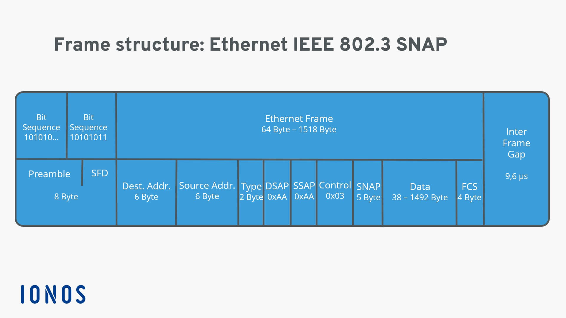
The first part of an Ethernet frame is known as the preamble. A preamble is 8 bytes or 64 bits long and can itself be split into two sections. The first seven bytes are a series of alternating ones and zeros. These act partially as a buffer between frames and can also be used by the network interfaces to synchronize internal clocks they use, to regulate the speed at which they send data. This last byte in the preamble is known as the SFD or start frame delimiter. This signals to a receiving device that the preamble is over and that the actual frame contents will now follow. Immediately following the start frame delimiter, comes the destination MAC address. This is the hardware address of the intended recipient. Which is then followed by the source MAC address, or where the frame originated from.
The next part of an Ethernet frame is called the EtherType field. It’s 16 bits long and used to describe the protocol of the contents of the frame. Instead of the EtherType field, you could also find what’s known as a VLAN header. It indicates that the frame itself is what’s called a VLAN frame. If a VLAN header is present, the EtherType field follows it. VLAN stands for virtual LAN. VLANs are usually used to segregate different forms of traffic. So you might see a company’s IP phones operating on one VLAN, while all desktops operate on another.
The data payload of a traditional Ethernet frame can be anywhere from 46 to 1500 bytes long. This contains all of the data from higher layers such as the IP, transport and application layers that’s actually being transmitted. Following that data we have what’s known as a frame check sequence. This is a 4-byte or 32-bit number that represents a checksum value for the entire frame. This checksum value is calculated by performing what’s known as a cyclical redundancy check against the frame.
If the checksum computed by the receiving end doesn’t match the checksum in the frame check sequence field, the data is thrown out. It’s then up to a protocol at a higher layer to decide if that data should be retransmitted. Ethernet itself only reports on data integrity. It doesn’t perform data recovery.
It also employs techniques like CSMA/CD (Carrier Sense Multiple Access with Collision Detection) to manage data collisions and maintain efficient communication. CSMA/CD is used to determine when the communications channels are clear and when the device is free to transmit data. The way CSMA/CD works is actually pretty simple. If there’s no data currently being transmitted on the network segment, a node will feel free to send data. If it turns out that two or more computers end up trying to send data at the same time, the computers detect this collision and stop sending data. Each device involved with the collision then waits a random interval of time before trying to send data again. This random interval helps to prevent all the computers involved in the collision from colliding again the next time they try to transmit anything.
Ethernet and the data link layer provide a means for software at higher levels of the stack to send and receive data. One of the primary purposes of this layer is to essentially abstract away the need for any other layers to care about the physical layer and what hardware is in use. By dumping this responsibility on the data link layer, the Internet, transport and application layers can all operate the same no matter how the device they’re running on is connected. So, for example, your web browser doesn’t need to know if it’s running on a device connected via a twisted pair or a wireless connection. It just needs the underlying layers to send and receive data for it.
2. Internet Layer
Function: The Internet Layer handles the logical addressing of data packets and is responsible for routing them across the network. It determines the best path for data to travel from the source to the destinationas.
Key Protocols:
- IP (Internet Protocol): The primary protocol for routing and addressing packets of data. IP ensures that data packets are sent to the correct destination by assigning unique IP addresses to each device on the network. Each packet, or datagram, contains a source and destination IP address. The IP protocol is inherently unreliable, providing only a best-effort delivery service without guarantees.
- ICMP (Internet Control Message Protocol): Used for diagnostic purposes, such as sending error messages or testing connectivity with tools like ping.
- ARP (Address Resolution Protocol): Maps IP addresses to the physical MAC addresses of devices, enabling the correct delivery of data on a local network.
The third layer, the network layer is also sometimes called the Internet layer. While the data link layer is responsible for getting data across a single link, the network layer is responsible for getting data delivered across a collection of networks.
It’s this layer that allows different networks to communicate with each other through devices known as routers. A collection of networks connected together through routers is an internetwork, the most famous of these being the Internet. The most common protocol used at this layer is known as IP or Internet Protocol. IP is the heart of the Internet and most small networks around the world.
The IP network layer is based on a datagram approach, providing only best-effort service, i.e. without any guarantee of the quality of service (QoS). IP is responsible for moving packets of data from router to router according to a four-byte destination IP address (in the IPv4 mode) until the packets reach their destination.
On a local area network or LAN, nodes can communicate with each other through their physical MAC addresses. But MAC addressing isn’t a scheme that scales well.
IP Address: IP addresses are 32-bit long numbers made up of four octets, and each octet is normally described in decimal numbers. IP addresses belong to the networks, not the devices attached to those networks. IP addresses are more hierarchical and easier to store data about than physical addresses are. IP addresses are distributed in large sections to various organizations and companies instead of being determined by hardware vendors. Management and assignment of IP addresses is the responsibility of the Internet authorities.
On many modern networks, you can connect a new device and an IP address will be assigned to it automatically through a technology known as dynamic host configuration protocol. An IP address assigned this way is known as a dynamic IP address. The opposite of this is known as a static IP address, which must be configured on a node manually. In most cases static IP addresses are reserved for servers and network devices, while dynamic IP addresses are reserved for clients.
Under the IP protocol, a packet is usually referred to as an IP datagram. The two primary sections of an IP datagram are the header and the payload. The very first field IP datagram header is four bits, and indicates what version of Internet protocol is being used. The most common version of IP is version four or IPv4. Version six or IPv6, is rapidly seeing more widespread adoption.
After the version field, we have the Header Length field. This is also a four bit field that declares how long the entire header is. This is almost always 20 bytes in length when dealing with IPv4. Next, we have the Service Type field. These eight bits can be used to specify details about quality of service or QoS technologies. The important takeaway about QoS is that there are services that allow routers to make decisions about which IP datagram may be more important than others.

The next field is a 16 bit field, known as the Total Length field. It’s used for exactly what it sounds like; to indicate the total length of the IP datagram it’s attached to. The identification field, is a 16-bit number that’s used to group messages together. IP datagrams have a maximum size. Since the Total Length field is 16 bits, the maximum size of a single datagram is the largest number you can represent with 16 b its: 65,535.
If the total amount of data that needs to be sent is larger than what can fit in a single datagram, the IP layer needs to split this data up into many individual packets. When this happens, the identification field is used so that the receiving end understands that every packet with the same value in that field is part of the same transmission.
Next up, we have two closely related fields. The flag field and the Fragmentation Offset field. The flag field is used to indicate if a datagram is allowed to be fragmented, or to indicate that the datagram has already been fragmented. Fragmentation is the process of taking a single IP datagram and splitting it up into several smaller datagrams.
If a datagram has to cross from a network allowing a larger datagram size to one with a smaller datagram size, the datagram would have to be fragmented into smaller ones. The fragmentation offset field contains values used by the receiving end to take all the parts of a fragmented packet and put them back together in the correct order.
The Time to Live or TTL field is an 8-bit field that indicates how many router hops a datagram can traverse before it’s thrown away. Every time a datagram reaches a new router, that router decrements the TTL field by one. Once this value reaches zero, a router knows it doesn’t have to forward the datagram any further. The main purpose of this field is to make sure that when there’s a misconfiguration in routing that causes an endless loop, datagrams don’t spend all eternity trying to reach their destination. An endless loop could be when router A thinks router B is the next hop, and router B thinks router A is the next hop, spoiler alert.
After the TTL field, you’ll find the Protocol field. This is another 8-bit field that contains data about what transport layer protocol is being used. The most common transport layer protocols are TCP and UDP.
So next, the header checksum field is a checksum of the contents of the entire IP datagram header. Since the TTL field has to be recomputed at every router that a datagram touches, the checksum field necessarily changes, too.
After all of that, we finally get to two very important fields, the source and destination IP address fields each 32 bits long. Up next, we have the IP options field. This is an optional field and is used to set special characteristics for datagrams primarily used for testing purposes. The IP options field is usually followed by a padding field. Since the IP options field is both optional and variable in length, the padding field is just a series of zeros used to ensure the header is the correct total size.
The entire contents of an IP datagram are encapsulated as the payload of an Ethernet frame. The contents of IP datagram payload are the entirety of a TCP or UDP packet.
Network devices
Network devices allow for many computers to communicate with each other. Hubs and switches are the primary devices used to connect computers on a single network, usually referred to as a LAN, or local area network.
A hub is a physical layer device that allows for connections from many computers at once. All the devices connected to a hub will end up talking to all other devices at the same time. This causes a lot of noise on the network and creates what’s called a collision domain. This causes these systems to have to wait for a quiet period before they try sending their data again. It really slows down network communications and is the primary reason hubs are fairly rare.
In much more common way of connecting many computers is with a more sophisticated device known as a network switch, The difference is that while a hub is a layer one or physical layer device, a switch is a layer two or data link device. This means that a switch can actually inspect the contents of the ethernet protocol data being sent around the network, determine which system the data is intended for and then only send that data to that one system. This reduces or even completely eliminates the size of collision domains on the network. If you guess that this will lead to fewer re-transmissions and higher overall throughput,
But we often want to send or receive data to computers on other networks, this is where routers come into play. A router is a device that knows how to forward data between independent networks. While a hub is a layer 1 device and a switch is a layer 2 device, a router operates at layer 3, a network layer. Just like a switch can inspect Ethernet data to determine where to send things, a router can inspect IP data to determine where to send things. Routers store internal tables containing information about how to route traffic between lots of different networks all over the world.
The most common type of router you’ll see is one for a home network or a small office. These devices generally don’t have very detailed routing tables. The purpose of these routers is mainly just to take traffic originating from inside the home or office LAN and to forward it along to the ISP, or Internet service provider. Once traffic is at the ISP, a way more sophisticated type of router takes over.
Core ISP routers don’t just handle a lot more traffic than a home or small office router, they also have to deal with much more complexity in making decisions about where to send traffic. A core router usually has many different connections to many other routers. Routers share data with each other via a protocol known as BGP, or border gateway protocol, that let’s them learn about the most optimal paths to forward traffic.
Key Protocols:
- Ethernet: A widely used protocol for wired local area networks (LANs), defining how data is transmitted over physical cables.
- Wi-Fi (IEEE 802.11): A protocol for wireless LANs, enabling devices to communicate over radio waves.
- PPP (Point-to-Point Protocol): Used for direct communication between two network nodes, often used in dial-up or leased line connections.
3. Transport Layer : TCP and UDP
Function: The Transport Layer is responsible for providing end-to-end communication between devices. It ensures that data is delivered error-free, in sequence, and with no losses or duplications. This layer manages the segmentation of data, flow control, and error handling.
While the network layer delivers data between two individual nodes, the transport layer sorts out which client and server programs are supposed to get that data.
The transmission control protocol (TCP) and user datagram protocol (UDP) are transport layer protocols of the Internet protocol reference model. They originate at the end-points of bidirectional communication flows, allowing for end-user terminal services and applications to send and receive data across the Internet.
Key Protocols:
- TCP (Transmission Control Protocol): Provides reliable, ordered, and error-checked delivery of data. TCP is connection-oriented, meaning it establishes a connection before data transmission and maintains it until the communication is complete. It establishes a connection between client and server and manages error checking and recovery, making it ideal for applications where data integrity is crucial. TCP is responsible for verifying the correct delivery of data between client and server. Data can be lost in the intermediate network. TCP adds support to detect errors or lost data and retransmit them until the data is correctly and completely received. Therefore TCP provides a reliable service through the network underneath may be unreliable, i.e., the operation of Internet protocols does not require reliable transmission of packets, but reliable transmission can reduce the number of retransmissions and thus improve performance.
- UDP (User Datagram Protocol): A simpler, connectionless protocol that allows for faster transmission but without the reliability and error-checking features of TCP. UDP provides a best-effort service as it does not attempt to recover any error or packet loss. Therefore, it is a protocol providing unreliable transport of user data. But this can be very useful for real-time applications, as re-transmission of any packet may cause more problems than losing packets. This is useful for real-time applications like video streaming or online gaming, where speed is more important than perfect data accuracy.
4. Application Layer
Function: The Application Layer is the closest to the end-user. It provides the interface for communication and data exchange between the user and the network. This layer is responsible for ensuring that the data is in a format that the application understands.
The application layer protocols are designed as functions of user terminals or servers. The classic Internet application layer protocols include HTTP for the Web, FTP for file transfer, SMTP for email, Telnet for remote login, DNS for domain name services
Key Protocols:
- HTTP/HTTPS (Hypertext Transfer Protocol/Secure): Used for accessing websites and transferring web pages.
- FTP (File Transfer Protocol): Used for transferring files between computers.
- SMTP (Simple Mail Transfer Protocol): Used for sending and receiving emails.
- DNS (Domain Name System): Translates domain names into IP addresses, enabling users to access websites using human-readable addresses.
Network software is usually divided into client and server categories, with the client application initiating a request for data and the server software answering the request across the network. A single node may be running multiple client or server applications. So, you might run an email program and a web browser, both client applications, on your PC at the same time, and your email and web server might both run on the same server. Even so, emails end up in your email application and web pages end up in your web browser.
The Interplay of Protocols: How TCP/IP Works
When you send an email or access a website, the data doesn’t just magically appear at its destination. Instead, it travels through the layers of the TCP/IP model, with each layer adding its own information to ensure successful transmission.
For example, when you send an email:
- The Application Layer (SMTP) formats the message and addresses it.
- The Transport Layer (TCP) breaks the message into segments, adds sequencing information, and ensures it can be reassembled correctly at the destination.
- The Internet Layer (IP) encapsulates these segments into packets, adds the destination IP address, and determines the best route for each packet.
- The Network Interface Layer transmits these packets over the physical network medium to the next hop towards the destination.
Upon reaching the destination, the process is reversed, with each layer peeling away its own information until the original data is reconstructed and delivered to the recipient.
Conclusion
The TCP/IP model is the backbone of modern networking, facilitating the seamless exchange of data across the globe. Understanding this model and its associated protocols not only helps us appreciate the complexity of digital communication but also equips us with the knowledge to troubleshoot network issues, optimize performance, and develop more efficient networking solutions.
Whether you’re streaming a video, sending a message, or browsing the web, it’s the TCP/IP model at work behind the scenes, making sure your data reaches its destination securely and reliably.