 International Defense Security & Technology Your trusted Source for News, Research and Analysis
Very Small Aperture Terminal (VSAT) systems are a critical component of satellite communication networks, providing reliable and widespread connectivity for various applications. To ensure optimal performance and reliability, comprehensive testing and measurement of VSAT systems are essential. This article delves into the key aspects of VSAT testing and measurement, focusing on the link between the VSAT and the satellite earth station.
VSAT Systems Overview
Satellite communications involve four primary steps: an uplink Earth station or ground equipment transmits the desired signal to the satellite. The satellite then amplifies this incoming signal and alters its frequency. Subsequently, the satellite sends the signal back to Earth, where ground equipment receives it. Satellite communications networks comprise user terminals, satellites, and a ground network responsible for control and interface functions.
Satellite User Terminal
A satellite user terminal typically includes an antenna subsystem, a tracking system, a transmitting section, and a receiving section. To minimize costs and bulk, a common antenna is used for both transmission and reception, with a diplexer facilitating the separation. The tracking system ensures the antenna remains pointed at the satellite despite relative movements.
VSAT Terminals
A Very Small Aperture Terminal (VSAT) is a two-way satellite ground station with a dish antenna typically ranging from 75 cm to 1.2 m, and generally smaller than 3.8 meters. VSATs operate in the C, Ku, and Ka frequency bands, offering data rates from 4 Kbps to 16 Mbps. These terminals access satellites in geosynchronous or geostationary orbits to relay data between remote Earth stations (terminals) in a mesh topology or to a master Earth station “hub” in a star topology.
Common everyday examples of VSAT terminals include dish antennas used for Direct-to-Home (D2H) satellite television broadcasts. Businesses also utilize VSATs for enterprise resource management and media networks, providing live coverage and various data transmission services. VSATs transmit narrowband data, such as point-of-sale transactions, RFID data, or Supervisory Control and Data Acquisition (SCADA) data, as well as broadband data for satellite Internet access in remote locations, Voice over IP (VoIP), or video.
VSAT Components and Operation
VSAT systems include several components: a small antenna (0.75 to 2.4 meters in diameter), orthomode transducer (OMT), block up-converter (BUC), low-noise block down-converter (LNB), interfacility link cable (IFL), and indoor unit (IDU). The IDU, which acts as a VSAT modem, sends signals to the BUC for upconversion and amplification before transmission via the dish antenna. Received signals are processed by the LNB, which filters, amplifies, and down-converts the signals for further processing by the satellite modem. This up/down conversion is necessary because signals must be transmitted at high frequencies through the air, while the indoor unit processes signals at much lower frequencies.
All outdoor components on the dish are collectively known as the Outdoor Unit (ODU), including the OMT that splits the signal between the BUC and LNB. The IDU, or modem, typically features an ethernet port and two F-connectors for coaxial cables to the BUC (transmit) and from the LNB (receive).
The Astra2Connect system features an integrated OMT/BUC/LNA assembly that resembles a Quad LNB in shape and size, mounted on a regular TV satellite mount. However, it operates at a lower power of 500 mW compared to the typical 2W, making it less effective in rainy conditions. Similarly, Skylogic’s Tooway system employs an integrated OMT/BUC/LNB assembly called a Transmit and Receive Integrated Assembly (TRIA), which operates at 3W.
The antenna is generally common to transmission and reception for reasons of cost and bulk. Separation of transmission and reception is achieved by means of a diplexer. The tracking system keeps the antenna pointing in the direction of the satellite in spite of the relative movement of the satellite and the station.
Maritime and Mobile VSATs
Transportable, on-the-move VSATs and maritime VSATs are designed for use in environments where the terminal is in continuous motion, such as on ships. The antenna part of a marine VSAT system must be stabilized with respect to the horizon and true north as the ship moves beneath it. These systems use motors and sensors to stabilize and accurately point the antenna at the satellite, enabling effective communication despite the movement. This enables it to transmit to and receive from the satellite while minimising losses and interference with adjacent satellites. New technology is emerging that will allow a solid-state device (flat panel) to steer an antenna electronically without moving parts.
Satellite Earth Station
The satellite earth station comprises larger antennas, high-power amplifiers, and sophisticated signal processing equipment to manage and route the satellite traffic. These terminals are used in applications such as satellite television, enterprise resource management, media networks, and transmitting narrowband and broadband data.
The figure of merit (G/T) of an Earth station is a crucial performance metric defined at the station receiver input. The figure of merit (G/T) of an Earth station and Remote VSAT terminal is defined as the ratio of the receiving gain to the system noise temperature. The gain of an antenna is highest in the direction of maximum radiation, known as the electromagnetic axis or boresight. Therefore, precise antenna alignment with the satellite’s foresight is essential to optimize performance. Earth station antennas must be efficient, with high directivity and low interference with nearby satellites.
Constructing and maintaining large Earth station antennas is a costly endeavor, making it imperative to achieve maximum efficiency. For example, an INTELSAT A station with a 30-meter diameter antenna operating at 4/6 GHz typically has a G/T value of 40.7 dBK⁻¹. Achieving such efficiency requires meticulous design and operation.
The minimum receivable signal level is set by inherent noise in the system. Earth stations are required to detect small signals so the control of the noise parameters is important. . For an earth station, the noise acquired by the antenna originates from the sky and surrounding ground radiation. It depends on the frequency, the elevation angle and the atmospheric conditions (clear sky or rain). The system noise temperature T is a function of the antenna noise temperature TA, the feeder losses LFRX, the thermodynamic temperature TF of this feeder and the effective noise temperature TeRX of the receiver.
Earth station antennas, located at the terrestrial end of satellite links, must meet several critical characteristics:
- High directivity towards the nominal satellite position to optimize useful signal reception.
- Low directivity in other directions to minimize interference with nearby satellites and systems.
- High antenna efficiency for both uplink and downlink frequency bands.
- High isolation between orthogonal polarizations.
- Low antenna noise temperature to reduce system noise.
- Accurate continuous pointing towards the satellite.
- Minimal impact from local meteorological conditions such as wind and temperature.
The antenna gain directly influences the effective isotropic radiated power (EIRP) and the figure of merit (G/T) of the station. The antenna beamwidth determines the appropriate tracking system based on the satellite’s orbital characteristics.
Polarization isolation is critical for antennas operating in systems with frequency re-use by orthogonal polarization. To prevent interference, polarization isolation must exceed a specified threshold. For instance, INTELSAT standards recommend an axial ratio (AR) of less than 1.06 for new antennas in the satellite’s direction, corresponding to a carrier power-to-interference power ratio (C/NI) greater than 30.7 dB. This ensures the system can handle the interference introduced by orthogonal polarizations, maintaining signal integrity and performance.
Earth Station Measurements and Testing
Testing and measurements for Earth stations involve pointing and tracking systems, particularly for non-GEO satellites, and optimizing antenna pointing using a beacon signal. Measurements include monitoring antenna sidelobe levels to prevent interference with adjacent satellites and using techniques like spectrum analyzers to capture antenna patterns.
Key Considerations
Several factors influence the testing approach for VSAT-to-Earth station communication:
- Frequency Bands: VSATs operate in specific frequency bands, such as C, Ku, or Ka. Testing verifies compatibility and identifies potential interference from other radio sources in those bands.
- Modulation Techniques: Different VSATs might employ various modulation schemes (e.g., QPSK, DVB-S2) to encode data onto carrier signals. Testing confirms proper modulation and demodulation functionalities.
- System Specifications: Both VSATs and Earth stations have defined performance specifications. Testing ensures these specifications are met, guaranteeing optimal signal strength, data throughput, and error-free communication.
Testing VSAT Performance: A Multi-Pronged Approach
A comprehensive testing approach for VSATs involves several key steps:
- Baseband Loopback: This internal test verifies the functionality of the VSAT’s baseband processing unit, which modulates and demodulates data signals.
- Intermediate Frequency (IF) Loopback: This test extends the baseband loopback, including the modulator, demodulator, and IF (intermediate frequency) processing stages.
- Radio Frequency (RF) Loopback: Here, the entire transmission and reception chain of the VSAT is tested, including the antenna and RF components.
- Bit Error Rate (BER) Testing: This crucial test measures the number of errors occurring in the transmitted data, ensuring data integrity and minimizing transmission failures.
- Environmental Testing: VSATs might operate in harsh environments. Temperature, vibration, and humidity testing ensure functionality under various conditions.
Key Measurement Parameters
To ensure the VSAT system performs optimally, several key parameters must be measured and monitored:
- Antenna Alignment and Pointing Accuracy
- Carrier-to-Noise Ratio (C/N)
- Bit Error Rate (BER)
- EIRP and G/T Measurements
- Interference and Adjacent Satellite Interference
- Network Latency and Throughput
1. Antenna Alignment and Pointing Accuracy
Accurate antenna alignment is crucial for maximizing signal strength and minimizing interference. Tools such as spectrum analyzers and antenna pointing devices are used to fine-tune the antenna orientation. This ensures that the antenna is correctly pointed towards the satellite, optimizing the link budget and maintaining a stable connection.
- For geosynchronous satellites, a simple pointing system is used, optimizing by tracking a beacon signal.
- New installations may use a spectrum analyzer to manually optimize antenna pointing.
Procedure:
- Use a compass and inclinometer for initial alignment.
- Fine-tune the azimuth and elevation angles using a spectrum analyzer to maximize the received signal strength.
- Verify the pointing accuracy by monitoring the received signal quality metrics such as C/N ratio.
2. Carrier-to-Noise Ratio (C/N)
The C/N ratio is a critical measure of the signal quality received by the VSAT. It indicates the level of the desired signal relative to the background noise. A higher C/N ratio signifies better signal quality and link reliability.
Measurement Technique:
- Use a spectrum analyzer or a specialized satellite modem with C/N measurement capabilities.
- Monitor the C/N ratio continuously to ensure it remains within acceptable limits, typically above 10 dB for a reliable link.
3. Bit Error Rate (BER)
BER is a measure of the number of erroneous bits received divided by the total number of bits transmitted. It is a direct indicator of the quality and reliability of the communication link.
The bit error rate (BER) measures the performance of the demodulator by counting the number of bits in error, n, in a stream of N received bits: BER = n/N
The BER constitutes an estimate of the bit error probability (BEP). A level of confidence is associated with this estimate, as follows:
BEP = BER +/- ( k * sqrt(n) / N)
A 63% level of confidence is obtained for k= 1 and a 95% level of confidence for k = 2. For instance, if n = 100 errors are observed within a run of N = 10 exp(5) bits, the BEP is 10 exp(-3) +/- 10exp(-4) with a 63% confidence level.
Measurement Technique:
- Use a BER tester or the built-in BER measurement functionality of the satellite modem.
- Perform BER tests under different conditions to assess the link’s robustness and identify any potential issues.
4. EIRP and G/T Measurements
Effective Isotropic Radiated Power (EIRP) and Gain-to-Noise Temperature (G/T) are key parameters for assessing the performance of the VSAT system. EIRP measures the power radiated by the antenna, while G/T is a measure of the system’s sensitivity.
Measurement Technique:
- Use a power meter and a noise figure meter to measure EIRP and G/T.
- Ensure that the measured values meet the specifications required for reliable satellite communication.
Determination of Earth Station Antenna G/T
The G/T parameter, representing the ratio of antenna gain (G) to system noise temperature (T), is critical for evaluating the performance of an Earth station antenna. There are two primary methods for determining G/T: direct measurement and mathematical approximation.
Direct Measurement Method
To achieve an accurate measurement of antenna G/T, a reliable source of RF emissions is required. This source can be another antenna with known parameters or a celestial body, such as the sun or a radio star. Celestial bodies are preferred due to their consistent visibility over extended periods and their predictable RF emissions. The sun is the most commonly used celestial source, as it is visible from nearly any location on Earth for significant portions of the day.
However, geographical challenges arise in extreme latitude locations where the sun may not be visible for several weeks. These locations are ideal for Low Earth Orbit (LEO) tracking, but alternative celestial sources are needed for accurate G/T measurements. For larger systems (with antenna diameters greater than 10 meters), several radio stars are visible in each hemisphere (e.g., Cassiopeia A, Taurus A, Orion, Virgo, Omega) and have well-defined flux density equations that facilitate precise measurements.
Smaller systems (with antenna diameters 5 meters or less) cannot rely on radio stars, as the measured power density (Pd) cannot be accurately determined with sufficient precision. For these smaller systems, the moon serves as the only viable celestial source of RF emissions, providing a practical alternative for G/T measurements.
Rx Gain and System Temperature Method
This test procedure involves measuring the receive (Rx) gain and system noise temperature of the Antenna Under Test (AUT), and then calculating G/T by subtracting the measured results. There are two direct methods to measure the Rx gain: integrating the Rx sidelobe pattern or determining the 3dB and 10dB beamwidths.
- Integration of the Rx Sidelobe Pattern: This method provides more accurate results but requires the AUT to have a tracking system. The integration process involves mapping the sidelobe pattern of the antenna and integrating it to obtain the Rx gain. This comprehensive approach accounts for variations across the antenna’s reception pattern, leading to a precise measurement.
- Determination of the 3dB and 10dB Beamwidths: This method involves measuring the antenna’s beamwidth at 3dB and 10dB points. Although less accurate than pattern integration, it is simpler to perform and does not necessarily require a tracking system. The beamwidth measurements provide a straightforward way to estimate the Rx gain by analyzing the antenna’s performance at specific points of signal strength reduction.
By accurately measuring the Rx gain and system noise temperature, and using the appropriate method to determine these values, the G/T parameter can be reliably calculated. This enables a precise assessment of the Earth station antenna’s performance, ensuring it meets the necessary operational standards and optimizes communication link quality.
System Noise Temperature
The system noise temperature can be calculated from measurement of the difference in noise power when the input to the receive system is terminated in hot and cold loads. This is known as a Y-factor measurement, where Y represents the difference in the noise power. The test
configuration for measuring the system noise temperature is illustrated in Figure
In the above test configuration, a spectrum analyser could be used as a less accurate alternative to the noise gain analyser. In order to measure the system noise temperature the AUT is pointed to clear sky, and the antenna is then considered to be the cold load. An input waveguide load at ambient temepature provides the hot load. This waveguide load typically forms an integral part of the LNA redundancy switching system, and can be switched in out using the LNA controller.
The AUT switches the LNA input to the ambient load and measures the noise power exhibited due to the hot load. The AUT then switches the LNA input to the antenna and measures the noise power exhibited due to the cold load. The difference between the measurements is the Y-factor. Using the measured Y-factor, the temperature of the hot load (ambient) and the LNA temperature (manufacturer’s results) the system temperature can be calculated using the formula below.
5. Interference and Adjacent Satellite Interference
Interference can significantly degrade the performance of a VSAT link. It is essential to monitor and mitigate both in-band and out-of-band interference, as well as adjacent satellite interference.
Antenna Sidelobe Levels:
- High gain and low sidelobe levels are essential to avoid interference with adjacent satellites.
- Sidelobe levels are measured by transmitting a signal from the antenna and recording the received signal level as the antenna is rotated.
Because geosynchronous satellite orbital slots are specified at every 2° of longitude, earth station antennas must have high gain and low sidelobe levels. If the gains of the antenna sidelobes are too high, the earth station antenna will produce high levels of interference to the adjacent satellites, especially when those systems share the same frequency spectrum and antenna polarization. For example, a single-beam earth station reflector antenna having a diameter greater than 100 wavelengths should have a sidelobe level determined by the following equation 29 – 25 log θ.
One way to measure the relative sidelobe level of an earth station antenna is to transmit a signal from the desired antenna and record the received signal level at another earth station as the desired antenna is rotated over a narrow angular displacement. The displacement should cover the main beam and the peaks of the two adjacent sidelobe levels. The same technique can be applied to capture the receive antenna pattern by using a fixed transmit antenna and a rotated receive antenna. In general, the measurement of sidelobe level in the transmitter antenna is of most importance as this signal potentially creates interference to other satellite systems if the sidelobes are out of specification.
Interfernce Measurement:
- Use a spectrum analyzer to scan the frequency band for any interfering signals.
- Implement filtering and shielding techniques to minimize the impact of interference.
6. Network Latency and Throughput
Network latency and throughput are critical parameters for assessing the performance of the VSAT system, especially for applications requiring real-time communication.
Measurement Technique:
- Use network performance monitoring tools to measure latency and throughput.
- Conduct end-to-end tests to ensure the network meets the required performance criteria.
Testing Earth Station Performance: A Broader Scope
Earth stations have a wider range of functionalities compared to VSATs. Their testing encompasses:
- Antenna Performance: Measurements assess antenna gain, pointing accuracy, and polarization (orientation of the electric field) to ensure efficient signal transmission and reception.
- Transmitter Power and Spurious Emissions: Testing verifies that the Earth station transmits within legal power limits and minimizes unwanted radio frequency emissions that could interfere with other systems.
- Receiver Sensitivity: Measurements determine the minimum signal strength the Earth station can receive and decode reliably.
- System Integration Testing: This ensures all Earth station sub-systems, including communication interfaces and control software, function seamlessly together.
Subsystem Test and Measurement
VSAT Modem Overview
A VSAT (Very Small Aperture Terminal) modem, also known as a satellite modem, is a critical component in VSAT applications. It facilitates the transmission and reception of data via satellite communications. VSAT modems are available in various frequency bands based on their intermediate frequency (IF) specifications, including 70 ± 18 MHz, 140 ± 18 MHz, and the L band (950 to 1450 MHz).
Components of an L Band Satellite Modem
The design of an L band satellite modem includes several key modules:
- Baseband Part:
- FEC Modules: Includes forward error correction (FEC) components such as convolutional encoders and decoders.
- Differential Encoder and Decoder: Ensures data integrity by encoding and decoding data differentially.
- Scrambler and Descrambler: Reduces the occurrence of long sequences of zeros or ones, ensuring a more uniform signal.
- Modulator and Demodulator:
- Modulator: Takes input information (data or voice) and converts it into a modulated carrier at the IF frequency.
- Demodulator: Receives the modulated carrier signal and extracts the original information (data or voice).
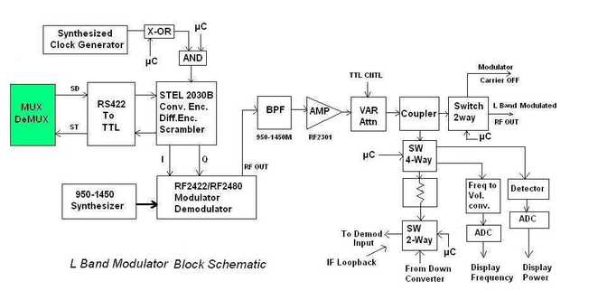
Additional Features and Functions
- Synthesizer: A synthesizer is used to select different RF carriers as required. This flexibility allows the modem to adjust to various frequency bands for different applications.
- Variable RF Attenuators: These are used to provide different attenuation or gain values. They are essential for testing and maintaining the VSAT network, ensuring optimal performance under various conditions.
- Switches: Employed for various baseband and IF loop-back testing purposes, switches help diagnose and troubleshoot faulty conditions in the VSAT modem.
- Interfaces: The VSAT modem typically interfaces with multiplexers and demultiplexers using interfaces like RS422 or V.35. This connectivity allows for the integration of multiple data streams and their efficient transmission via satellite.
By incorporating these components and features, a VSAT modem ensures reliable and efficient satellite communication, making it a vital part of the VSAT system
VSAT modems facilitate communication by modulating and demodulating signals at various IF frequencies. These modems consist of baseband processing subsystems, modulators, demodulators, synthesizers, and switches for testing and maintenance.
Maintenance and Installation Tests for VSAT Modem
During the maintenance and installation phases of a VSAT modem, several tests are conducted to ensure the modem’s functionality and reliability. These tests encompass various aspects of the modem, from its baseband components to its RF capabilities, and assess its performance under different conditions. Tests for VSAT modems include baseband loopback, IF loopback, RF loopback, bit error rate (BER) testing, and functional tests under different environmental conditions.

Key Tests Conducted:
- Baseband Loopback:
- Purpose: Tests the baseband part of the VSAT modem.
- Details: This test checks the integrity of the baseband processing elements, including FEC modules, encoders, and decoders. It ensures that data processing at the baseband level is functioning correctly.
- IF Loopback:
- Purpose: Tests both the baseband and the modulator-demodulator components.
- Details: By looping back the intermediate frequency (IF) signals, this test verifies the overall signal processing chain from baseband through modulation and demodulation stages, ensuring that the signal path is intact and performing as expected.
- RF Loopback:
- Purpose: Tests the modem including the RF part of the VSAT terminal.
- Details: This comprehensive test includes the RF transmission and reception capabilities of the modem. It checks the performance of the RF components and the antenna system, ensuring that the modem can effectively communicate with the satellite.
- Bit Error Rate (BER) Testing:
- Purpose: Assesses the error rate in data transmission.
- Details: BER testing is conducted for both short and long durations to evaluate the quality of the communication link. A low bit error rate indicates a reliable and robust data transmission capability of the VSAT modem.
- Voice Call Flow and Data Flow Testing:
- Purpose: Verifies the modem’s ability to handle voice and data communication.
- Details: This test ensures that the VSAT modem can successfully manage voice calls and data transmission, validating its operational readiness for real-world applications.
- Functional Tests Under Various Environmental Conditions:
- Purpose: Ensures modem performance under different environmental stresses.
- Details: The VSAT modem is subjected to various environmental tests, including temperature variations and vibration tests, to ensure its durability and reliability in different operating conditions. These tests confirm that the modem can withstand harsh environments and continue to perform optimally.
By conducting these comprehensive tests, the maintenance and installation processes ensure that the VSAT modem is fully functional, reliable, and ready to provide seamless satellite communication.
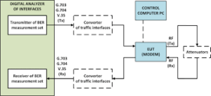
VSAT modem traffic Interface testing
One of the VSAT modem also called EUT is Teledyne Paradise Datacom PD10L modem. The VSAT modems can be equipped with various traffic interfaces. Currently, Ethernet, i.e., 10/100 Base-T, is most commonly used. Due to the high popularity, most modems are also equipped with G.703 interface.
Traffic interfaces :
• standard option: Ethernet (IP traffic on RJ45),
• additional options: G.703 (balanced on EIA530 120Ω or unbalanced on BNC 75Ω female), RS422, X.21, V.35, and RS232 (on EIA530 connector, 25-pin D-type female),
• other optional interfaces: Serial LVDS (25-pin D-type female), Quad E1 G.703 (balanced on RJ45), HSSI (50-pin HD SCSI-2 connector), Eurocom (D/1,D,C,G).
This procedure is implemented in the following steps:
a) preparation of the digital analyzer of interfaces – turn on its power supply and leave it in this state for the time necessary to obtain proper stability, and then carry out its self-test;
b) set up the tested satellite terminal modem (EUT) according to its user manual;
c) check if EUT has a proper connector (port) for the analyzed traffic interface type or if EUT has been equipped with an appropriate interface converter; if YES then go to (d) point of the procedure; if NO then the verification of the analyzed interface in the tested modem is negative – in the test report, note that there is no appropriate interface connector and go to (k) point of the procedure;
d) connect EUT to the measuring instrument according to the scheme shown in Fig. 4, selecting the appropriate connector and the type of traffic interface;
e) turn on the EUT power supply and leave it in this state for the time necessary to obtain adequate stability;
f) configure the modem to work with a fixed data transmission speed (bit rate), B;
g) tune EUT to the required frequency f = 0.5 * ( fmax +fmin) where max f and min f are maximum and minimum intermediate frequencies of the modem, respectively.
h) set the output (Tx) and input (Rx) parameters for the traffic interface in the digital analyzer of interfaces;
i) measure BER for a selected transmission speed – start the test on the analyzer and then, after the measurement, note the BER result;
j) repeat steps from (f) to (i) for EUT tuning frequencies (g) point of the procedure by decreasing f1 and increasing f2 by 5%
k) repeat steps from (c) to (j) for all analyzed types of traffic interfaces.
Analysis of the obtained results of BER measurement consists in checking the condition
Frequency Converter Measurements
Frequency converters play a crucial role in satellite communication systems by translating a modulated signal’s intermediate frequency (IF) to the uplink or downlink radio frequency (RF) of the system. The process involves either a block downconverter (BDC) or a frequency-synthesized downconverter, each with specific functions and measurement requirements to ensure optimal performance.
Block Downconverter (BDC)
A block downconverter (BDC) translates a broad range of frequencies captured from the satellite downlink to a lower frequency band for further signal processing and demodulation. BDCs typically employ a single internal local oscillator (LO) for this frequency translation. The intermediate frequency (IF) output from commercial BDCs is usually within the L-band frequency range, spanning from 950 MHz to either 1450 MHz or 2150 MHz.
Frequency-Synthesized Downconverter
In contrast, frequency-synthesized downconverters are designed with an IF in the VHF range, typically 70 MHz or 140 MHz. These downconverters utilize two LOs (double-conversion) to tune into a specific communication channel. They are capable of handling channel bandwidths of 40 MHz or 80 MHz, offering a high dynamic range and excellent adjacent channel rejection.
Ideal and Real Performance
Ideally, a downconverter should only shift the center frequency of the signal without altering or distorting it. However, RF/IF components along the conversion path can introduce distortions. Therefore, design engineers must select components that minimize these distortions. Several types of test equipment are essential to fully characterize the performance of a frequency converter:
- Intermodulation Distortion (IMD):
- Measurement Tool: Spectrum Analyzer
- Details: Measures the nonlinear distortion products generated by the interaction of multiple frequencies within the converter.
- Harmonic and Spurious Levels:
- Measurement Tool: Spectrum Analyzer
- Details: Identifies unwanted harmonic and spurious signals that can degrade the signal quality.
- Return Loss:
- Measurement Tool: Vector Network Analyzer
- Details: Assesses the efficiency of signal reflection at the converter’s input and output ports, ensuring minimal signal loss and reflection.
Key Specifications and Measurements
To ensure the optimal performance of any earth station frequency converter, several key specifications must be measured:
- Conversion Gain:
- Details: The ratio of output signal power to input signal power, indicating the amplification level provided by the converter.
- Gain Flatness:
- Details: The uniformity of the gain across the entire frequency band. Consistent gain ensures that all parts of the signal spectrum are amplified equally.
- Gain Stability Over Temperature:
- Details: The ability of the converter to maintain a consistent gain despite temperature variations, ensuring reliable performance in different environmental conditions.
Measurement Procedure
The measurement of these parameters requires specialized test equipment. A signal generator is used to sweep across a range of input frequencies, while the output frequencies’ amplitude response is measured. This process helps in assessing:
- Conversion Gain: Evaluating how effectively the frequency converter amplifies the signal.
- Gain Flatness: Ensuring consistent performance across the operational frequency range.
- Gain Stability: Verifying that the gain remains stable under varying temperature conditions.
By employing these measurements and characterizations, engineers can ensure that the frequency converters in VSAT systems operate efficiently, with minimal distortion and optimal performance.
Coaxial and Waveguide Components
Environmental conditions, such as rain and humidity, can significantly affect the interconnecting transmission lines in a VSAT system, including coaxial and waveguide components. Maintenance and troubleshooting of these transmission lines may occur more frequently due to these environmental impacts. Two primary measurement techniques used for this purpose are line sweeping and distance-to-fault (DTF).
- Line Sweeping: This measurement assesses the frequency response of a long transmission line, such as a coaxial cable or waveguide, that connects a transmitter to its antenna or an antenna to its receiver. Line sweeping reports signal attenuation and return loss along the entire transmission path. It provides a comprehensive view of the transmission line’s performance, identifying areas of signal degradation.
- Distance-to-Fault (DTF): DTF is a mathematical transformation of the measured frequency response into the time domain. It helps pinpoint the exact location of faults or imperfections along the transmission line by translating frequency response data into a distance metric. This is crucial for efficient maintenance and repair, allowing technicians to quickly locate and address issues.
Filter Measurements
Filters are essential components in all communication systems, including earth stations. They are typically integrated into high-performance upconverters and downconverters, primarily to achieve out-of-band rejection in both uplink and downlink paths. Filter performance is measured using a vector network analyzer (VNA), which displays the scattering parameters (S-parameters) of the two-port device.
Key measurements and characteristics of filters include:
- Insertion Loss: The loss of signal power resulting from the insertion of a filter in the transmission path.
- Return Loss: The measure of the signal reflected back toward the source, indicating the effectiveness of impedance matching.
- Group Delay: The time delay of the signal as it passes through the filter, which should be linear across the pass band to avoid signal distortion.
- Out-of-Band Rejection: The filter’s ability to attenuate frequencies outside its pass band.
- Bandwidth and Ripple Response: The width of the filter’s pass band and the variations in amplitude within the pass band, typically determined using marker functions on the VNA.
A critical aspect of filter performance is the transmission phase and the associated group delay response. A linear phase response across the pass band is essential to prevent signal distortion, and this is equivalent to having a flat group delay response.
Instruments for VSAT-to-Earth Station Testing
VSAT Testing:
- Spectrum Analyzer: Measures signal power spectrum, identifies interference, and verifies modulation characteristics.
- Signal Generator: Generates test signals with specific frequencies and modulation schemes.
- Bit Error Rate Tester (BERT): Measures the number of errors in transmitted data.
- Environmental Chambers: Simulates temperature, vibration, and humidity for environmental testing.
Earth Station Testing:
- Satellite Signal Simulator: Emulates real satellite signals for testing receiver performance.
- Power Meter: Measures transmitter power output.
- Antenna Tracking System: Verifies antenna pointing accuracy.
- Spectrum Analyzer (as with VSAT testing).
- Network Analyzers: Measure antenna impedance and scattering parameters.
Beyond the Lab: Field Testing for VSAT-Earth Station Links
While lab testing provides valuable insights, real-world performance verification is crucial. Field testing involves:
- Site Surveys: Assessing potential obstructions and signal interference at the VSAT deployment location.
- Link Budget Calculations: Verifying if the available signal strength at the VSAT location is sufficient for reliable communication with the Earth station.
- Live Traffic Testing: Transmiting and receiving actual data over the satellite link to assess performance under real-world conditions.
Military Testing of VSAT Terminals
When the armed forces purchase communication equipment from the civilian market, the equipment often requires special procedures, tests, or adaptations to meet the specific conditions of military operations. This equipment, even when supplied by leading global companies, must comply with national regulations that mandate tests confirming relevant parameters and functionalities.
- IEC 60835-3 Subseries: This set of standards provides methodologies for measuring typical parameters of terrestrial satellite terminals, including antennas, low noise and high power amplifiers, and up- and down-converters. One of these standards specifically focuses on very small aperture terminals (VSATs), ensuring they meet the rigorous demands of military applications.
These standards help ensure that the equipment performs reliably under the harsh conditions and specific operational requirements of military use, providing secure and effective communication capabilities.
Conclusion
Thorough testing and measurement procedures for VSATs and Earth stations are essential for establishing reliable and robust satellite communication links. Comprehensive testing and measurement of VSAT systems are essential for ensuring optimal performance and reliability. By focusing on key parameters such as antenna alignment, C/N ratio, BER, EIRP, G/T, interference, and network performance, engineers can diagnose and rectify issues, thereby enhancing the overall efficiency of the satellite communication network. Regular monitoring and maintenance are vital to maintaining the quality and reliability of VSAT links, ensuring seamless connectivity for various applications.
By employing a combination of lab tests, field evaluations, and meticulous attention to detail, engineers ensure clear and uninterrupted data exchange between remote locations and satellite networks. This meticulous approach forms the foundation for countless applications, from internet access in rural areas to critical communication for disaster relief efforts.
