 International Defense Security & Technology Your trusted Source for News, Research and Analysis
Spacecraft are man-made machines that operate in space. An orbiting spacecraft is normally referred to as a satellite, although it is manmade as opposed to a natural satellite like our moon. A spacecraft is typically subdivided into two major parts, the payload and the bus. The bus provides the structural body and primary system of a space vehicle, usually providing locations for the payload (typically space experiments or instruments).
The spacecraft bus consists of several different subsystems, each with a unique purpose. A bus typically consists of the following subsystems: Structures and mechanics subsystem (S&MS), Command and data handling (C&DH) system, Telemetry, Tracking, and Command (TT&C), Communications system and antennas, Electrical power system (EPS), Propulsion System (PS), Thermal control systems (TCS), Attitude control system (ACS), and Guidance, navigation, and control (GNC) system.
Command and data handling, which consists of the computer “brain” that runs the spacecraft, and all the electronics that control how data is transported from component to component. All other subsystems “talk” to this subsystem by sending data back and forth through hundreds of feet of wiring carefully routed throughout the spacecraft bus.
Telemetry, Tracking and Command (TTC) are vital functions of a spacecraft. They allow data to be communicated between the ground and the spacecraft for spacecraft control and command. The communication is through a telecommunication link established between the control station on the ground and the satellite.
TT&C can also cover links between separate spacecraft, such as the connection between an orbiter and lander, or the inter-satellite links of different satellites allowing them to share data and work together.
The communications subsystem contains components such as receivers and transmitters to communicate with controllers back on Earth. Many operations the spacecraft must perform are controlled through software commands sent from Earth by radio signals.
Telemetry, Tracking, Commanding and Monitoring (TTCM) subsystem
Satellite telemetry, tracking, and command (TT&C) is a crucial part of any space mission. It involves the gathering, collection, and processing of spacecraft onboard data to ensure the unerring operation of a spacecraft. TT&C is the only way to observe and to control the spacecraft’s functions and condition from the ground. Satellite Control Center (SCC) monitors the working and status of space segment subsystems with the help of telemetry downlink. And, it controls those subsystems using command uplink.
It is essential that a reliable communication link between the ground station and the spacecraft is maintained throughout the satellite’s different phases of operation. In general, satellite gets data through sensors. So, Telemetry subsystem present in the satellite sends this data to earth station(s). Therefore, TTCM subsystem is very much necessary for any communication satellite in order to operate it successfully.
Telemetry, Tracking, Commanding and Monitoring (TTCM) subsystem is present in both satellite and earth station. Typically, the TT&C subsystem aboard a spacecraft includes one or more transponders associated with quasi-omnidirectional antennas to ensure RF link availability from the ground. The TTC transponder on the spacecraft plays the role of radiofrequency interface with the ground. Virtually all spacecraft are equipped with TTC transponders.
The TT&C system on the ground typically includes a communication device known in the TT&C community as a baseband, a device that performs radio functions including transmission, reception, and ranging.
The TT&C system on the ground typically includes a communication device known in the TT&C community as a baseband, devices that perform radio functions including transmitters, receivers, transponders, antennas, and ranging. A baseband typically consists of a telemetry receiver, a telecommand transmitter, and a ranging transceiver.
A baseband typically consists of a telemetry receiver, a telecommand transmitter, and a ranging transceiver.
Commanding Satellites Subsystem
The commanding subsystem is necessary in order to launch the satellite in an orbit and its working in that orbit. A command and control system permits the ground station to control the satellite. This subsystem adjusts the altitude and orbit of satellite, whenever there is a deviation in those values. It also controls the communication subsystem. This commanding subsystem is responsible for turning ON / OFF of other subsystems present in the satellite-based on the data getting from telemetry and tracking subsystems.
The control signals are formed based on different digital codes which informs satellite what action need to be taken. The set of commands words are send in the form of TDM frames. Initially, the validity of command words is checked in the satellite. After this, these command words can be sent back to earth station. Here, these command words are checked once again. If the earth station also receives the same (correct) command word, then it sends an execute instruction to satellite. So, it executes that command.
The commands are used for various functionalities such as to initiate telemetry sequence, perform orientation of antenna and activate thrusters for attitude control. In order to track and to maintain attitude of the satellite, on board thrusters are fired from the ground station.
During the Launch and Early Orbit Phase (LEOP), ground control sends the required mission commands, such as to fire the booster rockets for orbital correction, to deploy the antenna or solar array, or to fire the apogee boost motors. Some of these operations must happen at precise times, while others can take place during a window of time. This is done even to re-orient antennas of spacecraft, to have maximum exposure of solar panel to the sun and to make corrections of satellite based on infrared sensors
During the lifetime of the mission, which is generally four to ten years, the satellite receives daily the commands required to reconfigure functions according to requirements at the time. Earth observation satellites, such as SPOT or ERS, receive instructions for their next orbits, such as the region of interest of the Earth to observe, the direction of view, or the spectral band to use. A data-relay satellite, such as Artemis or DRS, receives daily commands to inform it of its low Earth orbiting clients; it receives the necessary data for pointing one or more of its antennas towards that satellite and following its path while data relay communication is required.
Telecommanding is of particular importance to deep-space probes. Their distance from the Earth creates communication problems (although the probes have a high degree of autonomy to overcome those problems). Firstly, the signals reaching the probe from the ground are so weak that the amount of data that can be transmitted is limited. Secondly, it can take up to several hours for the radio signal from Earth to reach the probe if the probe is at the edge of the solar system, which makes controlling the probe extremely difficult.
Monitor Constellation through Telemetry and Monitoring Subsystem
The telemetry link is equally important to the success of a satellite mission. It is used to monitor the status, health, and function of a satellite constellation and the systems it relies on. Satellites have quite a few sensors to monitor different parameters such as pressure, temperature, status of various subsystems. It comprises of transmitting results of measurements, information concerning satellite operation, the operation of equipment and verification of the execution of commands to the ground.
Telemetry is the data received from the spacecraft, generally about the status of its systems. For scientific satellites, including deep-space probes, the telemetry link also carries payload data. During launch and early orbit, telemetry allows ground technicians to check that commands are being carried out correctly, e.g. that boosters are being fired or that the antennas or solar panels are being deployed. Throughout the mission, it enables the mission control centre to survey the ‘insides’ of the satellite, its configuration, its status, and in the case of failure, it provides the basis for the decisions that have to be made.
Investigate Anomalies – investigate spacecraft alerts and anomalies, as well as analyze subsystem mnemonics, measurements, value limits, etc. In general, the telemetry data is transmitted as FSK or PSK.
Tracking and ranging subsystem
Enabling measurement of the ground–satellite distance, and possibly the radial velocity, in order to permit location of the satellite and determination of orbit parameters. Thus, by measuring the return propagation time, the distance between the ground station and the satellite can be estimated.
Ranging : The transponder demodulates the ranging signal contained in the uplink and remodulates it onto the downlink. Uplink pseudo-random code is detected and retransmitted on the downlink. The Turnaround time provides range. Ground antenna azimuth and elevation
determines satellite angular location.
Carrier Tracking is implemented via two-way coherent communication. Transmitter phase-locks to the received frequency. Moreover, the transponder has the ability to generate a downlink carrier phase coherent with the uplink carrier, allowing precise estimations of orbit and speed from measurements of Doppler offset and rate of the downlink frequency at the ground station. Transmitted frequency is a specific ratio of the uplink frequency. Easy to find and measure the frequency received on the ground. The Doppler shift provides range rate
Standards
These constituents of a baseband are required to offer support to multiple missions. This requirement poses compatibility challenges as most of today’s TT&C systems employ a variety of standards ranging from broadband satellite communications to military standards (e.g., NATO’s standard agreement (STANAG) 4486. Established in 1982, the Consultative Committee for Space Data Systems (CCSDS) provides a set of standard recommendations that ensure compatibility in communications and data systems for spaceflight. Observed by 27 nations, CCSDS strives to ensure interagency compatibility among member nations.
The most relevant set of standards for baseband systems falls under spacelink services. The physical layer provides recommendations on several physical layer parameters including data rates, line codes, frequency bands, modulation schemes, and hardware tolerances. These parameters are specified for both CCSDS categories A (below 2 million km) and B (above 2 million km). The synchronization and channel coding layer provides recommendations for frame synchronization and forward error correction (FEC). The datalink layer deals with virtual channels. Virtual channels are logical channels that multiplex multiple logical communication links onto a single physical channel.
The Radio Frequency and Modulation Systems book provides recommendations for data rates, line codes (NRZ-L/M/S and BP-L/M/S), frequency bands (S, X, K and Ka), matched-filters and modulation schemes. As an example, the book recommends the use of binary phase-shift keying (BPSK), quaternary phaseshift keying (QPSK), offset QPSK (oQPSK), pulse code modulation/ frequency and phase modulations (PCM/PM, PCM/FM), and Gaussian minimum shift keying (GMSK).
An example of recommended filters are integrate-and-dump (IDF), square root-raised cosine (SRRC), and raised cosine (RC). It also provides recommendations for hardware tolerances and channel impairments including frequency, phase, and time offsets, I/Q imbalance, phase noise mask, and Doppler shift and rate. The TM Synchronization and Channel Coding book recommends the use of convolutional, Reed-Solomon, Concatenated convolutional and Reed-Solomon, low-density parity-check (LDPC), and Turbo codes. The book also specifies a frame format known as channel data access unit (CADU) along with two classes of frame synchronizers. The TM Space Data Link Protocol and Space Datalink Security Protocol book recommends eight virtual link services, namely, virtual channel packet (VCP), virtual channel access (VCA), virtual channel frame secondary header (VC FSH), virtual channel operational control field (VC OCF), virtual channel frame(VCF), master channel frame secondary header (MC FSH), master channel operational control field (MC OCF), and master channel frame (MCF) services.
There is only a set of CCSDS books that recommend a pseudonoise (PN) ranging standard. The PN ranging standard applies to deep space missions (Category B). Other ranging standards such as multitone (e.g., ESA) and hybrid multitone-PN (ESA Code) ranging standards are not
specified by CCSDS.
The Radio Frequency and Modulation Systems book also includes recommendations for the telecommand transmitter physical layer. Among them are data rates for low-, medium- and high-rate modulation schemes. These correspond to PCM/PSK/PM,PCM/PM and BPSK modulation schemes, respectively. The TC Synchronization and Channel Coding book recommends the use of BCH or LDPC FEC code along with a specific packet format referred to as communications link transmission unit (CLTU). The TC Space Data Link Protocol and Space Datalink Security Protocol book recommends the use of seven virtual link services, namely, MAP Packet (MAPP), Virtual
Channel Packet (VCP), MAP Access (MAPA), Virtual Channel Access (VCA), Virtual Channel Frame (VCF), Master Channel Frame (MCF) and COP Management.
Telemetry and telecommand links
Telemetry and telecommand links are low bit rate links, a few kilobits per second at most. This differs for scientific satellite telemetry (such as observation of the earth) for which the data rates are much greater, typically a few tens of megabits per second.
One of the major characteristics required of TTC links is availability. Ensuring availability of the TTC links is fundamental for diagnostics in case of breakdown and for performing corrective actions. The necessary reliability is obtained by means of suitably replicated transmitting and receiving equipment (transponders). This equipment is associated with one or more antennas which have a radiation pattern such that the gain is as constant as possible, or at least greater than a minimum value, throughout most of the space around the satellite. This permits links to be established whatever the attitude of the satellite.
Frequencies used
The TTC links should nominally be operated within the Space Operation Service (SOS) frequency bands. The frequencies normally used are in S band as follows:
—the uplink in the band 2025 to 2120 MHz;
—the downlink in the band 2200 to 2300 MHz.
It is clear that the available bandwidth (of the order of 100 MHz) is insufficient to accommodate all the modulated carriers from the various satellites in orbit. Also, these bands are reserved for operations associated with injecting the satellite into orbit and an emergency mode in case of a problem in normal mode in the operational phase. During these phases, the orientation of the satellite attitude with respect to the earth is arbitrary. An omnidirectional antenna is thus
indispensable.
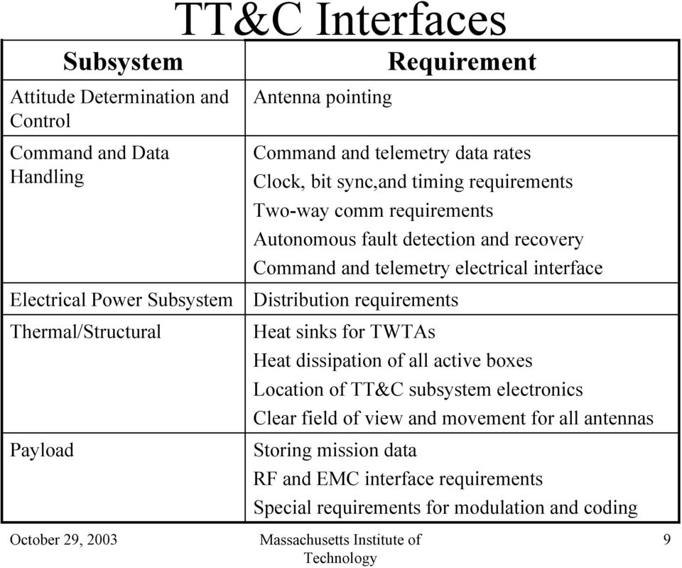
Subsystem Operations:
Receive commands from Command and Data Handling subsystem
Provide health and status data to CD&H
Perform antenna pointing
Perform mission sequence operations per stored software sequence
Autonomously select omni-antenna when spacecraft attitude is lost
Autonomously detect faults and recover communications using stored software sequence
TT&C Architecture
S-band TT&C subsystem consists of two TT&C s-band antennas, RF Distribution Unit (RFDU) and two transponders. Each transponder has a receiver, transmitter and duplexer. These two transponders are used to backup each other and to provide RF channels for mini- satellite tracking, telemetry, ranging, and command. The duplexer at each transponder is used to switch between receiver and transmitter.


The requirements and parameters of TT&C transponder (s-band command receiver and s-band telemetry transmitter) of the LibyaSat-1 are shown in Table III. The command receiving sensitivity is –110dBm, noise figure is less than 6 dB and the output power of the s-band telemetry transmitter is about 5 W. Transponders are connected to both antennas via hybrid coupler which distributes signals in both directions. The polarization of these antennas should be Circular Polarization (CP). This is important as it achieves the best signal strength and mitigates multipath fading.
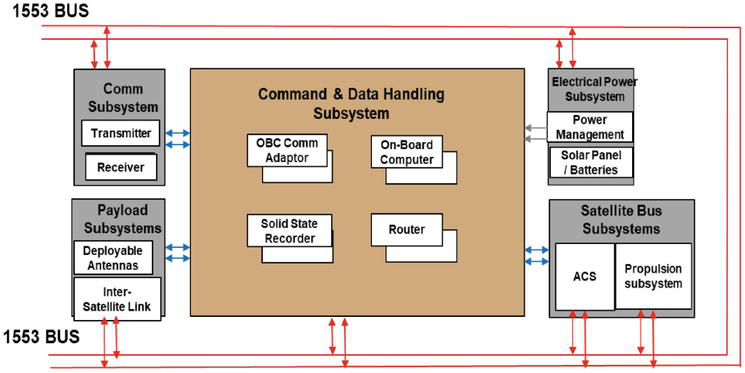
The heart of the system is the C&DHS’ onboard computer (or OBC) that runs the software responsible for managing the onboard operations. The OBC is tightly linked to the electrical power subsystem (EPS). The main reason is the importance of the available and consumed power for managing onboard spacecraft operations. For instance, by continuously querying the EPS on the available power, the OBC can decide to turn off non-critical subsystems to prevent vital systems from shutting down from lack of power. Secondly, the OBC must be able to command the EPS to disable or enable different subsystems throughout the various phases of the mission. Since the amount of transmitted data between these two subsystems is small, a low-speed data link is sufficient, although there is a new trend to incorporate high-speed standard link such as SpaceWire4 to satisfy increasing demand for data volume.
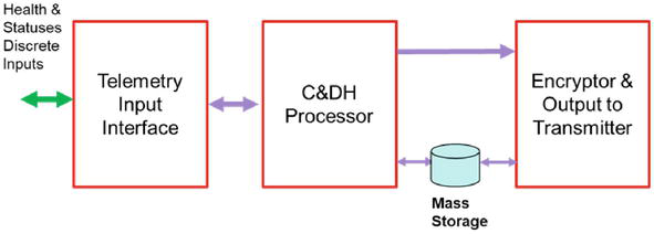
Here the different health information and status information sent from various subsystems are collected by the telemetry input interface, fed to the C&DHS processor, buffered, encrypted, and sent down to the ground station.
The OBC is also responsible for receiving, interpreting, and executing commands from ground operators via the radio receiver. Using low-speed radio transmitters, the OBC also sends packets of housekeeping data, or telemetry, to the ground station. The purpose of the housekeeping data is to give the operators on the ground an overview of the spacecraft health and its general condition.
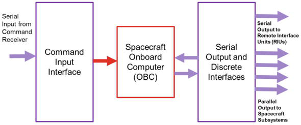
A typical command processing scenario is illustrated in Figure where serial command bitstream from the command receiver is received by the command input interface, where the relevant commands are extracted and sent to the appropriate subsystems via a serial or parallel interface.
Software Architecture
The major requirement involving a system that combines telemetry processing with satellite command and control is that the system hardware and software must support in real time the generation of commands derived in whole or in part from conditions that are revealed in the satellite’s telemetry data. This condition implies that the satellite’s telemetry downlink processing and the transmission of the command uplink are coupled tightly in a closed-loop system where real-time performance is critical. (The example system described in this article is such a system.)
In the Microwave Journal Authors describe example system in which the VTS software consists of low level drivers that control the boards in the system and higher level application software that allows setup and control of the telemetry, commanding and I/O boards. Asynchronous I/O utilities provide low overhead access to the telemetry and I/O hardware.
The VTS application software consists of real-time VME-based software running tinder the VxWorks operating system. This software controls the acquisition and processing of the PCM telemetry stream, generation of uplink commands, and the UNIX workstation-based setup and control graphical displays. The setup and control software running on the UNIX host communicates with the real-time processor over an industry-standard Ethernet link.
VTS software provides the high level control required to operate the system as a fully integrated product. The graphical setup and display portion of the software allows each real-time task to be configured and controlled graphically and intuitively from the host workstation using a series of icons, setup menus and display devices (referred to as widgets).
The industry-standard X-Windows/Motif-based GUI software provides system setup, telemetry and command parameter definition, display definition and real-time display capabilities. It performs error checking on user-input parameters and signals the user when an invalid parameter is entered. Hard copy output of the system’s configuration is supported. The system configuration allows the user to graphically set up each of the telemetry I/O interfaces, the other I/O interfaces and the network.
The parameter definition capability allows the user to enter and edit parameter-processing definitions. The parameter ID and input information, as well as the various algorithms to be applied to it, are defined. The display definition capability allows the user to select from a number of widgets (numeric display, gauge, bar graph, strip chart, x-y plot or scrolling tabular display) and define the colors, ranges, positioning, size and format of each output window. Parameters (with their respective out-of-limit values) are associated with the widget to define a display. Displays are grouped to windows and windows are grouped to a configuration. Save, restore and edit capabilities are available for each user-configuration item.
Standards
These constituents of a baseband are required to offer support to multiple missions. This requirement poses compatibility challenges as most of today’s TT&C systems employ a variety of standards ranging from broadband satellite communications to military standards (e.g., NATO’s standard agreement (STANAG). Established in 1982, the Consultative Committee for Space Data Systems (CCSDS) provides a set of standard recommendations that ensure compatibility in communications and data systems for spaceflight.
The most relevant set of standards for baseband systems falls under spacelink services. The spacelink services, correspond with OSI layers. The physical layer provides recommendations on several physical layer parameters including data rates, line codes, frequency bands, modulation schemes, and hardware tolerances. These parameters are specified for both CCSDS categories A (below 2 million km) and B (above 2 million km).
The synchronization and channel coding layer provides recommendations for frame synchronization and forward error correction (FEC). The datalink layer deals with virtual channels. Virtual channels are logical channels that multiplex multiple logical communication links onto a single physical channel. The CCSDS recommendations are published in color-coded books including those representing current recommendations (Blue), information reports (Green), recommended practices (Magenta), experimental (Orange), record (Yellow), and historical (Silver).
The Radio Frequency and Modulation Systems book provides recommendations for data rates, line codes (NRZ-L/M/S and BP-L/M/S), frequency bands (S, X, K and Ka), matched-filters and modulation schemes. As an example, the book recommends the use of binary phase-shift keying (BPSK), quaternary phaseshift keying (QPSK), offset QPSK (oQPSK), pulse code modulation/ frequency and phase modulations (PCM/PM, PCM/FM), and Gaussian minimum shift keying (GMSK). An example of recommended filters are integrate-and-dump (IDF), square root-raised cosine (SRRC), and raised cosine (RC). It also provides recommendations for hardware tolerances and channel impairments including frequency, phase, and time offsets, I/Q imbalance, phase noise mask, and Doppler shift and rate.
The TM Synchronization and Channel Coding book recommends the use of convolutional, Reed-Solomon, Concatenated convolutional and Reed-Solomon, low-density parity-check (LDPC), and
Turbo codes. The book also specifies a frame format known as channel data access unit (CADU) along with two classes of frame synchronizers.
The TM Space Data Link Protocol and Space Datalink Security Protocol book recommends eight virtual link services, namely, virtual channel packet (VCP), virtual channel access (VCA), virtual channel frame secondary header (VC FSH), virtual channel operational control field (VC OCF), virtual channel frame(VCF), master channel frame secondary header (MC FSH), master channel operational control field (MC OCF), and master channel frame (MCF) services.
The TC Space Data Link Protocol and Space Datalink Security Protocol book recommends the use of seven virtual link services, namely, MAP Packet (MAPP), Virtual Channel Packet (VCP), MAP Access (MAPA), Virtual Channel Access (VCA), Virtual Channel Frame (VCF), Master Channel Frame (MCF) and COP Management.
TT&C Technology trends
Traditional ground station equipment, with its custom components and proprietary architectures, is no longer cost effective in today’s highly competitive, cost- and schedule-sensitive international marketplace where satellite programs are undergoing ever-shortening development. and deployment cycles.
These facts mandate that the command, control and telemetry ground equipment used to support these missions be highly flexible, easily reconfigurable, supportable on an international level and, above all, based around a totally open system architecture with hardware and software components that adhere to published international standards.
End-to-end system engineering of TT&C systems, including coding, modulation, multiplexing, link and interference analysis.
Securing TT&C links, involving encryption and authentication, system design issues, end-to-end analysis and performance verification.
software-defined radio TT&C transponder, which can be used to emulate and test candidate TT&C architectures.
Software-defined radio for TT&C
We can define a radio architecture as a comprehensive, consistent set of radio functions, components, and design rules according to which a radio may be organized, designed, and constructed. The SDR architecture divides the radio functions and components into an RF frontend (RFFE) and a signal processing device. The RFFE performs radiofrequency functions
and sampling. The signal processing device performs signal processing and higher-level
functions.
Signal processing devices include general-purpose processors (GPP), programmable
gate arrays (FPGA), digital signal processors (DSP), application-specific integrated circuits (ASIC), and special-purpose units (SPU), such as a graphics card. The selection of a signal processing device is a tradeoff between throughput, power consumption, development effort, and cost. Either signal processing device can realize a TT&C baseband.
A powerful GPP or a private cloud of GPPs can be used to realize a full software-defined TT&C ground station. By moving the SDR RF frontend closer to the antenna, the need for longer RF or optical cables (which range from a few meters to a few kilometers), downconverters and upconverters can be eliminated. This result in a much GREENER TT&C station. It should be noted that, at this moment, most CoTS SDRs have a maximum frequency range of 6 GHz. Thus, anything above the S-band, e.g., X-, C-,K- and Ka bands which are expected to be more prevalent in the future, would require frequency up- and downconverters. However, there exist CoTS SDRs, such as Per Vices Cyan, that could reach 18 GHz, but they are prohibitively expensive.
Commercial-off-the-shelf (CoTS) SDR frontends have become less expensive and more accessible at standards capable of supporting satellite ground operations as specified by CCSDS physical layer hardware requirements (clock and frequency stability, phase purity e.t.c)
The use of SDR-based baseband systems with CoTS SDR frontends will address the following issues:
1. Low costs of development and maintanance. The development of current hardware-based baseband systems is quite high, since it involves low-level hardware and software development. The use of CoTS SDR frontends and open-source SDR application frameworks such as, GNU Radio, Open-Source SCA Implementation: Embedded (OSSIE), Xmidas, Liquid DSP, etc., can lower development costs and time.
2. Good track of operational code, since software updates are not dependent on the hardware. Software updates for the current hardware-based baseband systems are expensive, as they are licensed and may involve hardware change.
3. Homogeneity between different units, since version control is relatively easy to manage in an all-software system.
4. High level of operational redundancy, since the software can be executed on parallel
computers in a private cloud.
5. Room for technological improvement. The use of SDR-based baseband systems would allow integration of new techniques in digital signal processing and digital communications, including adaptive coding and modulation (ACM) and multiple spacecraft per aperture (MSPA) capabilities.
