International Defense Security & Technology Your trusted Source for News, Research and Analysis
Wire harnesses are bundled assemblies of cables and connectors, that are used to transmit signals and power
between components. If we could compare a satellite to the human body, the electrical harness would represent the blood vessels conveying the power and the nervous network transmitting the commands and sensor information to each organ and muscle.
Essentially all flight hardware requires electrical harnesses. Cables are bound together with a combination of straps, cable ties, cable lacing, sleeves, electrical tape, and conduit. The wire harness contains multiple breakouts and simplifies the connection to larger components by integrating the wiring into a single unit.
It’s therefore not surprising that the harness appears to be very complex and may consist of thousands of wires. In a large satellite, the harness may require more than 50 000 connections located on about 1000 connectors linked by 20km of wires, and the mass may exceed 100kg.
The constraints imposed on electrical harnesses for Space applications are increasing with the growing complexity and power needs of scientific and commercial spacecraft. It becomes mandatory to optimize satellites harness and take the full potential of the state-of-the-art harness technologies and components while guaranteeing that the design remains safe in a large diversity of environments and operating conditions.
As with most of the other onboard systems, the harness is submitted to a long list of requirements related to Electrical performance, mass, EMC and ESD protection, thermal and radiation environments, mechanical mounting, and a few more requirements that are specific to each mission.
The harness accommodation is also heavily constrained by the structure of the satellite and the location of the different units that are themselves driven by the mission’s requirements. Large, powerful satellites require long wires with large sections, impacting the mass. Small satellites (for small launchers) do not provide a lot of space for harness accommodation and inter-panel connections (i.e. harness on hinges, interface connectors).
The harness schedule is always on the critical path of the project. This is because the harness is the last design
to be frozen (all of the electrical interfaces and the spacecraft accommodation shall be frozen before) and one
of the first equipment to be installed on the satellite (no electrical testing is possible on the spacecraft without
the harness).
Optimize the harness
Onboard spacecraft, the electrical harness is certainly among the most complex electrical equipment only made of
Passive Components. It is also a key element driving the performance of the electrical system, as well as a significant contributor to the mass budget. The best utilization of passive components in the harness is therefore crucial. Despite -or due to- its complexity, the harness must comply with a strict zero default requirement and must be 100% safe.
The first way to optimize the harness is obviously to minimize the requirements: in the past years a very significant
saving has been achieved by a critical review and simplification of the harness specifications focusing on the
justification of each requirement. Another way to save mass is to minimize the length of the wires and cables. This is already considered as “normal work” during the accommodation of the satellite and the routing of the harness.
The harness mainly provides two functions: transmit information (e.g.: databus, telemetries, bi-level commands) and convey power (e.g.: primary & secondary power supply lines). Sometimes, the same wires can provide both, as for pulsed commands on pyrotechnics, relays or RF switches for example.
Except the data busses, the harness used for data transmission is usually made of numerous cables of small core
sections, often shielded. A good example is the on-going evolution from analogue to digital data transfers that shall more and more rely on data busses instead of point-to-point links. However, this approach requires significant efforts as it implies deep changes in the electrical architecture, the interface of electronics and it needs the qualification of new active components. On the other hand, the power distribution harness represents fewer wires but uses larger sections.
Another way is to optimize the utilization of existing components (wires, cables and connectors). This means
using the right component for the right need and avoiding over design. It requires a good characterisation of the
component’s loads and environment but also clear rules and guidelines to perform the sizing. This approach could be based on engineering work, simulation tools and validation tests.
Some thermal simulations of real harness bundles have been performed on telecom spacecraft and have already
allowed reducing over-design and harness mass by several kilograms, still keeping a significant margin versus the harness acceptance limits. These simulations have been validated by some vacuum tests. This experience strongly suggests that improving the derating rules is a “Quick Win” solution that could deliver a harness mass saving from 5% to more than 20% depending of the spacecraft.
For most Space programs, the sizing of the electronic, electrical and electromechanical components (EEE) components is ruled by the ECSS Space product assurance -Derating – EEE components. The aim is to “specify derating requirements applicable to (…) to obtain reliable and high-performance equipment without over sizing of the components.”
The ECSS standard specifies:
• The voltage derating
• The maximum surface temperature in all conditions
• The maximum current in specific conditions: Ambient temperature of 40°C; Single wire; and Bundles of N wires with full current and P wires without current.
The derating factor was then determined by analyses and tests to make sure that the maximum temperature at the
surface of the hottest wire (usually the one in the center of the bundle) will not exceed the acceptable temperature
(including some margin).
It has to be noticed that the derating factor is very severe, especially for conductors within bundles: the derating factor drops dramatically when the number of conductors in the bundles rises: for 10 wires, the derating factor is already below 0.5. This means that in a bundle of 10 conductors, a wire must be sized at less than half of the
current it could have carried if it would have been alone.
Ampacity improvements
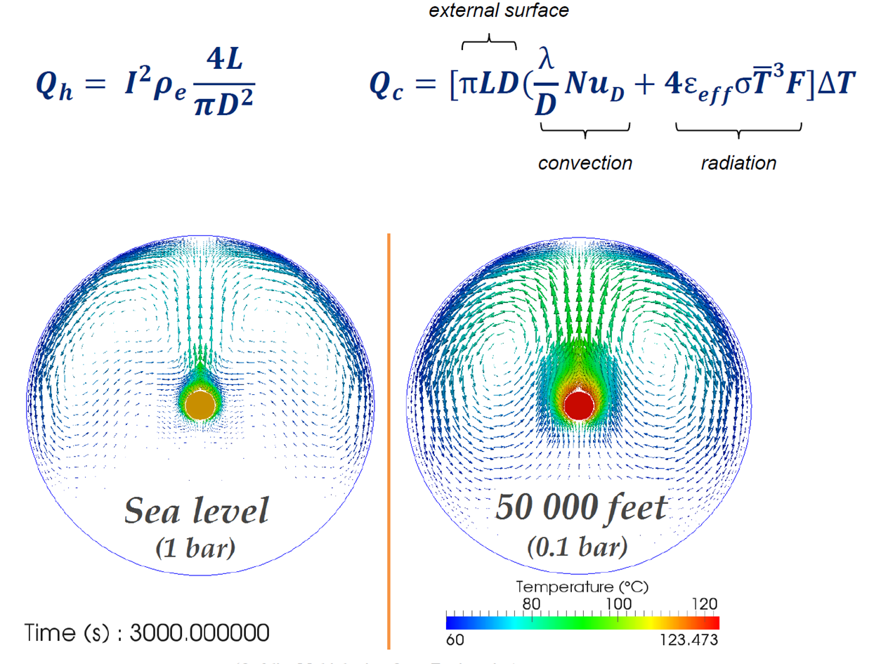
When electrical current flows down a conductor, it gets warm due to resistive heating. The more current that flows, the warmer the conductor gets. Depending on the wire gauge, conductor conductivity, and ambient temperature of the wire location, the conductor temperature reaches the maximum certified temperature. This maximum ELECTRICAL CURRENT is where the outward heat (through convection and radiation) matches the resistive heating of the conductor. This steady-state condition is the ampacity of a single wire. The problem becomes more complicated with the addition of more wires and the use of different wire types (signal, different wire gauges, conductor types) bundled into the wire harness.
The reason that ampacity limits are placed on wires, cables, and harnesses, is to:
- Ensure that the maximum conductor/insulation operational temperature is not violated,
- Maintain the long-term wire/cable reliability, and
- Determine if the use different wire gauges are necessary to meet the system electrical load requirements.
The ampacity calculations, as they are specified in AS50881, will ensure a safe EWIS design (from an overheating perspective); this is validated by decades of aircraft designed with this limitation.
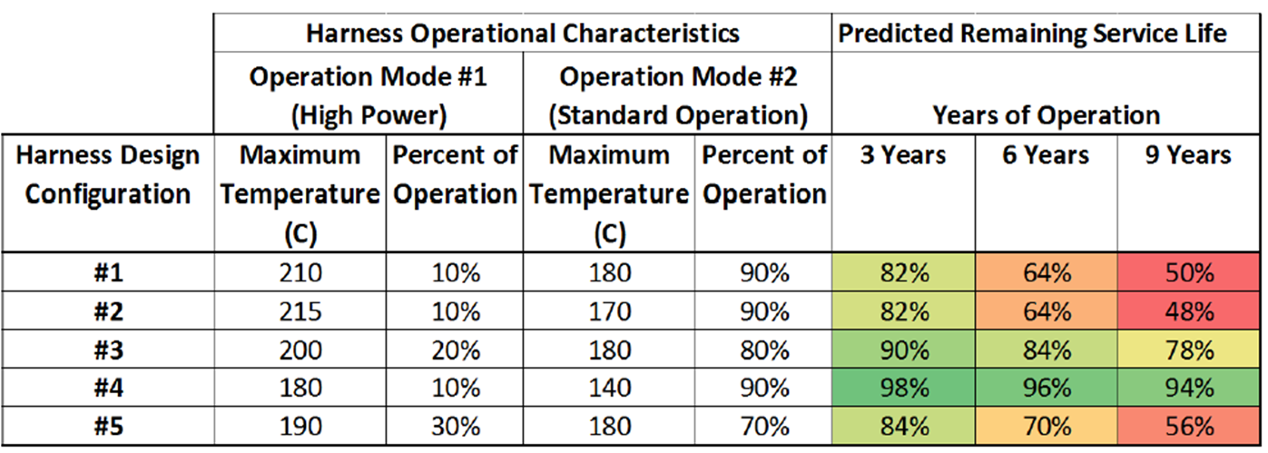
In the following example, five harness configurations were identified each with two primary operational modes: one high power that places a higher current on the wire harness and one standard operation that covers 80-90% of the operational time. While none of the operational configurations violate the maximum temperature of the wire harness design, three of the configurations (#1, #2, and #5) create a more rapid degradation of the EWIS components.
Derating
Due to the temperature rating of a wire, there is only a certain amount of electrical current that can be transmitted down the wire before the wire heats up beyond its temperature rating. This becomes a more complicated question when there are multiple wires in a single wire harness, supporting equipment (such as clamps), and other parts of the EWIS (connectors, secondary harness protection). The clear objective here is to avoid using too large a wire gauge because of the unnecessary added weight to an aircraft.
Given a wire harness configuration, what can be done to determine the DERATING? The conservative approach would be to use the SAE aerospace standard AS50881 and the guidance that is available therein. However, if additional secondary protection is placed onto the wire harness, such as Nomex braiding, chafe protection, etc., the rate of thermal energy loss from the wire harness is impacted. The existing guidance does not provide any feedback on how to address this.
The first step in the overall process is to understand the harness configuration. Does the wire harness contain only a few wires or is it a complicated harness set with tens or hundreds?
The next step requires understanding of the environmental conditions in which the harness is placed. Is there airflow in this location? What is the ambient operational temperature? Is the environment temperature and PRESSURE CONTROLLED? Each of these factors require consideration and has an impact on the energy loss during operation
Once the harness physical layout is understood and the environmental conditions are identified, the next step is to understand the circuit configuration. The first consideration is the number of power carrying wires and identify the current carried by these wires. As with a load analysis for an aircraft, it is important to know if these systems will function simultaneously. If it is unlikely or impossible for all of the circuits to be active simultaneously, then this needs to be a consideration with the derating and test harness set up. Otherwise, the derating factor will be very conservative and require the use of larger gauge wires than is necessary.
CONNECTOR derating is one area that remains ambiguous and is difficult to identify a good set of guidance. The difficulty for defining a degrading factor for connectors is that there is such a variety in connector design, contacts, inserts, back shell accessories, etc. that the thermal dissipation from these is hard to generalize (e.g., if the connector is mounted on structure, the thermal conductivity of aluminum and composite structures are significantly different).
NASA Goddard Space Flight Center(GSFC) Design and Manufacturing Standard
Designing and testing flight harnesses in accordance with the requirements of the GSFC Design and Manufacturing Standard for Electrical Harnesses enhances the probability of mission success (Reliability) by ensuring that harnesses meet high standards of quality as well as the electrical and environmental requirements of space flight missions. The occurrence of early failures is minimized.
Flight electrical harnesses are designed in accordance with the requirements and specifications of the GSFC Design and Manufacturing Standard for Electrical Harnesses which establishes the minimum requirements for the design and fabrication of space flight harnesses. Parts and materials are used as specified in the harness standard that can perform satisfactorily in the environments to be encountered. Fabrication methods and techniques are used as defined to ensure high-quality electrical harnesses. The GSFC Design and Manufacturing Standard for Electrical Harnesses incorporates and references applicable requirements from a wide range of Federal, Military, and NASA specifications, standards, and publications.
Maximum current-carrying capacity is defined for wire sizes ranging from size AWG 12 to AWG 24 to ensure that the total temperature of wire does not exceed the operating temperature ratings of the wire. The total temperature of the wire includes the ambient space temperatures and the temperature rises due to current flows. The maximum voltage drop between power supplies and loads due to the impedance of wire and ground return paths are specified for various power supply voltage levels. The minimum size of individual wires used in harnesses is AWG 24 except for power harnesses where the minimum size of wires is limited to AWG 22.
A number of EMI design and construction techniques are used to minimize electromagnetic coupling between wires within harness assemblies. These techniques include isolation of different signal types such as high level and pulse signals from low level and continuous wave signals by using separate harnesses and connectors where possible. When these signal types must be included within the sane harness, the best possible isolation is obtained by grouping wires of similar signal types within the harness and on connectors. Other methods include shielding of individual wires or groupings of wires within the harness and using separate connectors where possible. Twisted pair leads, shielded when necessary, are used for power and balanced signal circuits. RG type RF cables terminated at both ends with coaxial connectors are used for RF signals.
A number of physical parameters and limitations are used as defined in the Design and Manufacturing Standard for Electrical Harnesses. The diameter of the harness is kept to a minimum and limited to one inch in diameter consistent with requirements for routing, installation, and handling. The Design and Manufacturing Standard for Harnesses contains information and a method for estimating the diameter of a harness. The lengths of harnesses are made to provide enough additional wire length for reworking connections at least one time. Minimum bend radiuses, location and support of wire breakouts, shielding and termination of shields are followed as defined in the harness standard. Harnesses are secured with lacing tape or tie wraps and movement is controlled by means of cable clamps or tie wraps.
Electrical connector types including protective covers, sealing grommets, wire splices, and potting compounds are selected and fabricated as required by the harness standard. Probing or testing flight harnesses or connectors is always accomplished via connector savors or breakout boxes. Mate/demate logs are maintained and connector inspections are instituted once the connector mate/demate count reaches 15 and inspected every 10 mates/demates thereafter. Connector hardware is staked with an approved epoxy after torquing. The staking is an indication that the hardware has been torqued and that it has not been disturbed.
A number of quality assurance provisions are followed as defined in the Design and Manufacturing Standard for Electrical Harnesses. Visual inspection includes harness documentation, materials used, design and fabrication methods, identification of components, and workmanship. Harness assemblies are tested for point to point electrical continuity in accordance with applicable wiring diagrams or wire lists. Values, within a connector bundle of the same conductor size and wire length, must be consistent within 10%. Insulation resistance is measured between each conductor and every other conductor and each conductor and shield. The insulation resistance must be greater than 100 megohm at an applied voltage voltage of 500v dc for a maximum of one minute.
Essentially all harnesses have strict contamination control and certification requirements. To meet these requirements shielding braids are ultrasonically cleaned with an approved solvent and wires and cable are wiped with clean lint free cloths and an approved solvent before fabrication into the harness. After harness fabrication is complete and certified, the complete harness is cleaned with an approved solvent, inspected with both black and white light and vacuum baked at a temperature of 200 C above maximum environmental test temperature. The bakeout continues until a chamber pressure of 1X10⁻⁶ Torr is reached and the Quartz Crystal Microbalance (QCM) requirements are fulfilled.
Technical Rationale
The proper design, fabrication, testing, and certification of electrical harnesses significantly reduces the probability of spacecraft failures due to harness material deterioration in space, wire and connector failures due to current overloading, excessive stresses, and crosstalk and arcing between wires and harnesses. The use of appropriate materials and cleaning technique’s during and following fabrication of harnesses controls contamination that can cause deterioration and failure of spacecraft hardware particularly many types of scientific instruments.
NASA-STD 8739.4A: Crimping, Interconnecting Cables, Harnesses, and Wiring is NASA’s workmanship standard for wiring and cabling assemblies for spaceflight hardware and critical ground-support equipment.
IPC/WHMA-B-620, Requirements and Acceptance for Cable and Wire Harness Assemblies, now at Revision B published November 2012 , is the industry consensus standard for cable and wire harness fabrication and installation. Classes of products are defined and include criteria for Target, Acceptable, Process Indicator and Defect conditions to support the collection of visual quality acceptability requirements for each class.
IPC/WHMA-A-620 Space Addendum
Known as the Space and Military Applications Electronic Hardware Addendum to IPC/WHMA-A-620, the document consists of modified and additional requirements published in the IPC/WHMA-A-620 standard. These requirements ensure the performance of cable and wire harness assemblies in military and space environments.
J-STD-001 Space Addendum:
The IPC-J-STD-001GS space addendum supplements or replaces specifically identified requirements of IPC J-STD-001G for soldered electrical and electronic assemblies that must survive the vibration and thermal cyclic environments of getting to and operating in space and military applications. The additional requirements are used to ensure the reliability of soldered electrical and electronic assemblies that must sustain vibration and thermal cyclic environments within the space and military applications.
References and Resources also include:
https://escies.org/download/webDocumentFile?id=60980
https://llis.nasa.gov/lesson/722