International Defense Security & Technology Your trusted Source for News, Research and Analysis
Related Articles
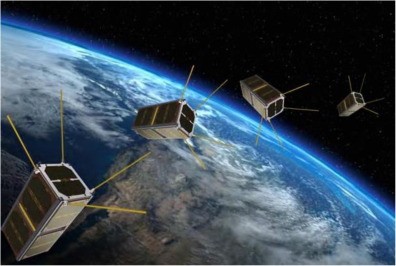
There is growing utilization of miniaturized satellites for military and defense applications. Defense organizations have been launching communication nanosatellites and microsatellites to provide communication signals to soldiers stationed in remote locations or in dense forests. The military needs more data bandwidth and reliable communications infrastructure for its UAVs, which can be fulfilled using constellations of nano and microsatellites.
However, a large percentage of missions are found to fail on launch or during early operations, particularly missions from university teams rather than those from commercial groups or space agencies. This is likely attributed to a lack of verification and validation (V&V) activities due to constraints on resources, experience, or schedule within these small scale projects
Satellite manufacturers must create a reliable product that supports these critical functions. Whether the satellite is for the government, the military or private industry, the need for rigorous testing remains the same. If a private company is going to build satellites for the government or commercial concern, they won’t retain that business for very long if the satellites they build don’t operate appropriately after launching into orbit.
A primary goal during satellite development is to save time (and money) and, looking at the nominal workflow for satellite production, the large amount of test campaigns that are spread over the whole development cycle is
one of the greatest time-consuming activity
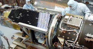
Electrical Ground Support Equipment (EGSE) are tools used by satellite and sub-system manufacturers and integrators to test and validate electrical functions of the satellite on the ground before launch. EGSE consists of hardware and/or software elements that perform satellite testing, by simulating the interfaces of missing (sub-)systems to assure full compatibility once integrated within the overall platform. This includes both satellite onboard elements as well as external elements related to communications.
Electrical Ground Support Equipment
Electrical Ground Support Equipment (EGSE) is test equipment (hardware + software) that allows a satellite provider to integrate and validate the electrical functions of the spacecraft and its sub-systems. An Electrical Ground Support Equipment is an essential tool that allows a satellite or space launcher developer to integrate and validate the electrical functions of its spacecraft.
It basically allows the telecommand sending and data reception, thus making possible the verification and validation of the Satellite systems. The basic requirements for the system include command upload with scripting capability, telemetry download with raw and engineering displays, static simulation of about 60 analog signals from avionics equipment on board, and dynamic stimulation of the simulated avionics signals for attitude control algorithm testing. Additionally, the capability to record and analyze telemetry and memory dumps is desirable.
data and pre-stored command sequences for testing the spacecraft. The equipment will also be utilized post-launch, with the development OBP, to test command sequences and anomaly correction plans before uplinking to the spacecraft
A typical EGSE is composed of a Central Check-Out Equipment (which is usually provided by the satellite provider) and several front ends or equipment-specific SCOE (Special Check-Out Equipment) which ensure the interface between the Central Check Out Equipment and the spacecraft.
- SAS | Solar Array Simulation SCOE
- BS | Battery Simulation SCOE
- BCE | Battery Conditioning Equipment SCOE
- LPS / UMB | Launch Power Supply / Umbilical Interface SCOE
- PYRO | Pyro Simulation SCOE
- Specific needs | Behaviour simulation, break out box, failure box, ambient and vacuum ground harness…
On-Board Interfaces
Satellites consist of various subsystems, such as Power, Communications, Data Handling, Onboard Computer, etc. All these sub-systems use a wide variety of interfaces, both internally (within a sub-system) and externally (between sub-systems). These On-Board Interfaces can differ at many levels, such as physical, electrical and on protocol level. To support (sub-)system manufacturers during development and validation phases, C-STS offers a wide range of front-end products.
RF Interfaces
Spacecraft RF Interface testing is a vital stage of spacecraft assembly, integration and test (AIT) both at sub-system level and full spacecraft level. During satellite AIT via Electrical Ground Support Equipment (EGSE), operators can communicate directly with the spacecraft. The operators use a fixed cabled connection. This is frequently done by using the Bypass connections from the TM/TC Front-End to the On-Board Computer. It is also done via the real RF interfaces of the spacecraft. The RF interfaces are typically connected to an RF SCOE (Special Check-Out Equipment), that includes up/down conversion, RF test and measurement equipment. The interfaces can also be connected to the TT&C Modems for AIT purposes.
RF SCOE
A satellite without working radio sub-systems is space debris: Like the 2011 “Zombie-Satellite”, the payload is working, but it is unresponsive, unable to communicate and thus it cannot complete its mission. To make sure this never happens to your satellites, the proven and industry-standard RF SCOE tests and calibrates their radio frequency sub-systems with a market-leading degree of precision.
Because it measures an absolute power level with an uncertainty of only 0.2 dB, gain vs. frequency with an uncertainty of only 0.3 dB and group delay vs. frequency with an uncertainty of only 0.5 ns, it significantly reduces the risk of a radio malfunction once the satellite is in orbit.
The RF SCOE performs fully automated S-, X-, Ku- and Ka-band measurements in the TT&C (Telemetry, Tracking & Command) section of the satellite during assembly of the spacecraft and during space environment testing at the test center facility. It does the same in the L-, S-, X-, Ku-, Ka-, and UHF-bands for the mission communication and payload section.
Because the RF SCOE is based on proven generic and mission-independent components, it integrates easily into your existing testing infrastructure and minimizes one-time investments. Due to the low lead-time of these components, it also optimizes time to delivery.
Satellite bus power subsystem EGSE
Satellite bus electric power subsystem EGSE supplies power needed for ground testing and validation during Assembly and Integration Test. It also offers load simulation to exhaust power stored in satellite, satellite’s power subsystem monitoring, signal acquisition and simulation, and solar array simulator.
Power SCOE
The Power SCOE is the reliable solution for powering, monitoring and testing your satellite’s power subsystem during assembly, integration & test as well as on the launch pad just prior to lift-off.
It consists of proven products based on generic and mission-independent components. A solar array simulator, battery simulator, launch power supplies, pyro / thermal knife SCOE and payload load simulator ensure that your satellite’s most vital system, the power supply, is in perfect condition for the launch and prepared to perform flawlessly for its entire lifespan. Additionally, the Power SCOE allows synchronous event data recording across all measurement channels for quick analysis of suspicious behavior.
In case of an anomaly, our Protection Unit for Satellite Testing (ProUST) provides an additional protection layer that works independently of the main power supply in order to prevent a single point of failure. With a protection reaction time of 20 μs, ProUST is your satellite’s safety net that steps in when all other systems fail.
Payload Interface
The Payload EGSE allows the fully automated execution of calibrations and tests and it easily integrates with heterogeneous components from different providers and suppliers. The Payload EGSE allows the fully automated execution of calibrations and tests and it easily integrates with heterogeneous components from different providers and suppliers.
Thus, by re-using a large part of your EGSE heritage it reduces your overall testing costs. Furthermore, all test sequences and procedures are defined in the Open Source Language TCL and can therefore be easily tailored and extended to best fit your requirements.
Integrated Systems
With a wide range of On-Board and RF Interface products in our portfolio, we can provide turn-key satellite testing solutions. These Integrated Systems, which nominally consist of our own front-end equipment complemented with COTS products, provide our customers a complete test environment to validate their satellite or subsystem. All integrated systems are designed and implemented to specification, where the in-depth knowledge of the Celestia-STS engineers adds value to find the best and most cost-efficient solution for the customer.
Software
Electrical Ground Support Equipment consists of various subsystems, such as TM/TC, CAN, MIL-1553 and WizardLink. All EGSE subsystems must be controlled via dedicated software. The software allows spacecraft operators to have control over a unit under test (UUT), run automated test scripts to speed up the testing, monitor real time statuses, perform data processing of recorded or simulated data and visualize data in many ways. For that purpose, C-STS offers a wide range of in-house developed software products which could be customized according your needs.
Celestia STS introduces new approach to spacecraft test & simulation
Celestia STS, a specialist in ground-based solutions for satellite testing, communications and data processing, has launched MPIP, a multi-purpose interface platform that offers a novel approach to spacecraft test and simulation.
MPIP is a modular, scalable electrical ground support equipment (EGSE) that enables space equipment builders or integrators to test and simulate different electrical interfaces in a fast, flexible, and cost-efficient manner. By combining interfaces into a single platform that’s completely scaleable, it offers a highly effective and versatile testing solution for all spacecrafts from large to small.
The various satellite onboard interfaces commonly used within testing programmes make use of the European Cooperation for Space Standardization (ECSS) standards, which define a multitude of standardised onboard electrical and protocol interfaces. These vary from low rate, up to 2Mbps, to medium rate, up to 400Mbps, up to high rate of 6.25Gbps and beyond. Traditionally these types of interfaces are implemented by dedicated EGSE units or platforms divided by type and bandwidth of an interface type, making them costly to implement and maintain.
Celestia STS’s new MPIP adopts a more flexible and efficient approach by integrating all interface types into a common architecture that supports the complete range of spacecraft on-board interfaces, such as Power, Discretes, SpaceWire and future High-Speed Interfaces like WizardLink, in a single platform. MPIP is designed to support future space programmes with data rates of up to 20Gbps and beyond.
MPIP is a rack-mount or tabletop 19”, 3U unit which supports up to 16 interface modules. Each module represents dedicated electrical or data ECSS interface types (LCL, ASM, TSM, HPC, SpW etc) and is designed in a 3U Eurocard size form factor, which adds to the scalability of the system. For small systems, the modules can be mounted horizontally, providing a total of eight slots in a 2U high unit.
By combining different MPIP modules in one platform we can offer our customers a versatile, cost-efficient, and easily maintainable spacecraft test and simulation system. It’s our answer to the new space trends,”
says Dougie Johnman, COO at Celestia STS. “Future satellite test and simulation systems need to meet the increasingly higher data rate requirements for current and future satellites, while maintaining the standard discrete electrical interfaces which monitor and control payload and platform sub-systems. Our new solution achieves both, making it a very attractive proposition for our current and prospective clients alike,”
Satellite Ground Equipment Market Size
The Satellite Ground Equipment Market size is analysed to grow at a CAGR of 19.6% during the forecast 2022-2027 to reach $54.8 Billion by 2027. The Satellite Ground Equipment is considered as the complete portfolio of the Electrical Ground Support Equipment (EGSE), which are integrated to ensure successful collecting and streaming satellite data. The Satellite Ground Equipment Industry has experienced a massive growth rate due to the impeccable advancement of radio communication solutions such as noc equipment, growing demand of mobile radio communications, and significant deployment of public safety applications.
Furthermore, the profitable introduction of Low Earth Orbit (LEO) satellite systems and High Throughput Satellites (HTS), along with the Ku- and Ka-band satellites are adding a lucrative growth opportunity. Simultaneously, the humongous demand of autonomous and connected vehicles that are used for various applications in the sectors, including commercial government and defence, require sophisticated customized SATCOM-on-the-move antennas for highly trusted operation, resulting in driving the Satellite Ground Equipment Market. The sizable investment by the leading market players, such as for aiming high-definition intelligence, surveillance, and reconnaissance (ISR) videos, demand for high-end satellite network infrastructure, developing Testing Satellite Servicing Tech and more are driving the market growth. Hence, the demand for prompt connectivity, the competitive presence of numerous well-established players and technological advancements, such as vsat equipment, are some of the promising factors that are estimated to accelerate the growth of the Satellite Ground Equipment Market.
References and Resources also include:
https://atos.net/en/solutions/aerospace-defense-electronics/egse
https://digitalcommons.usu.edu/cgi/viewcontent.cgi?article=2787&context=smallsat