 International Defense Security & Technology Your trusted Source for News, Research and Analysis
Satellite present in an orbit should be operated continuously during its life span. All the satellites require internal power in order to operate various electronic systems and communications payloads that are present in it. The Electrical Power System (EPS) is a vital subsystem whose primary role is to supply satellite systems with the necessary electrical power to operate effectively.
The source of the power is mainly the energy collected from the solar panels which are exposed to direct solar radiation or to indirect radiation from albedo. Batteries are installed alongside the solar panels to store energy which can then be used when the satellite regularly passes through the shadow of the Earth. Batteries can also help to provide sufficient power during periods of peak demand by the payload onboard the satellite. As of 2020, approximately 85% of all nanosatellite form factor spacecraft were equipped with solar panels and rechargeable batteries.
Electrical Power Supply (EPS)
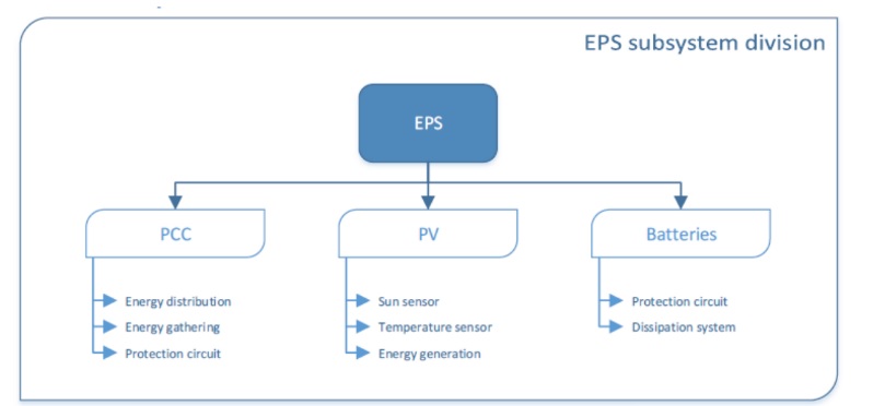
The EPS is a major, fundamental subsystem, and commonly comprises up to one-third of total spacecraft mass and volume. The electrical power system (EPS) encompasses electrical power generation, storage, and distribution. The Electrical Power Supply, or EPS of the CubeSat is composed by three modules which are the PCC (Power Control Circuit), the PV (photovoltaic panel) and the BAT (Battery). The role of the EPS is to generate, store and distribute the electricity produced by the solar panels.
Power generation technologies include photovoltaic cells, panels and arrays, and radioisotope or other thermonuclear power generators.
Power storage typically occurs in batteries; either single-use primary batteries or rechargeable secondary batteries.
Power management and distribution (PMAD) systems facilitate power control to spacecraft loads. PMAD takes a variety of forms and is often custom-designed to meet specific mission requirements.
EPS engineers often target a high specific power or power-to-mass ratio (Wh kg−1) when selecting power generation and storage technologies to minimize system mass impact. The EPS volume is more likely to be the constraining factor for nanosatellites.
PV (Solar Cells and Arrays)
Solar power generation is the predominant method of power generation on small spacecraft. Basically, the solar cells that produce electrical power from incident sunlight are used primarily in order to provide power to other subsystems of satellites. Since individual solar cells generate very little power they are grouped together in a solar array and solar panels. Spacecraft are built so that the solar panels can be pivoted as the spacecraft moves. Thus, they can always stay in the direct path of the light rays no matter how the spacecraft is pointed.
In the case of Cubesat, the power generated is limited since the area available of the solar panel is strongly limited on the CubeSat (each side size 100 cm², and has to integrate solar cells but also sensors and wires). In order to pack more solar cells into limited volume in SmallSats and NanoSats, mechanical deployment mechanisms can be added, which may increase spacecraft design complexity, reliability, as well as risks.
All electrical circuits generate waste heat; in addition, solar arrays act as optical and thermal as well as electrical collectors. Heat must be radiated from their surfaces. High-power spacecraft may have solar arrays that compete with the active payload itself for thermal dissipation.
Solar panels on spacecraft supply power for two main uses:
- Power to run the sensors, active heating, cooling and telemetry.
- Power for electrically powered spacecraft propulsion, sometimes called electric propulsion or solar-electric propulsion.
System Specifications
For both uses, a key figure of merit of the solar panels is the specific power (watts generated divided by solar array mass), which indicates on a relative basis how much power one array will generate for a given launch mass relative to another. Another key metric is stowed packing efficiency (deployed watts produced divided by stowed volume), which indicates how easily the array will fit into a launch vehicle. Yet another key metric is cost (dollars per watt).
EPS engineers often target a high specific power or power-to-mass ratio (W h kg−1) when selecting power generation and storage technologies to minimize system mass impact. The volume is more likely to be the constraining factor for nanosatellites.
The primary function of the PV module is to provide energy to the battery and the other modules. But other systems specifications shall be taken into account, which are: the MPPT’s (Maximum Power Point Tracker) wiring, the technology and the size of solar panels (Triple Junction), the protection against certain wavelength, the wiring of solar panels, and the decrease of the efficiency of solar panels.
Solar cells
Photovoltaic cells, or solar cells, are made from thin semiconductor wafers that produce electric current when exposed to light. The light available to a spacecraft solar array, also called solar intensity, varies as the inverse square of the distance from the Sun. The projected surface area of the panels exposed to the Sun also affects generation and varies as a cosine of the angle between said panel and the Sun.
Limitations to solar cell use include diminished efficacy in deep-space applications, no generation during eclipse periods, degradation over mission lifetime (due to aging and radiation), high surface area, mass, and cost.
Single and multi-junction
While single-junction cells are cheap to manufacture, they carry a relatively low efficiency, usually less than 20%. Up until the early 1990s, solar arrays used in space primarily used crystalline silicon solar cells. Since the early 1990s, Gallium arsenide-based solar cells became favored over silicon because they have higher efficiency and degrade more slowly than silicon in the space radiation environment.
Modern spacecraft designers favor multi-junction solar cells made from multiple layers of light-absorbing materials that efficiently convert specific wavelength regions of the solar spectrum into energy, thereby using a wider spectrum of solar radiation from 300 nm to 1700 nm. These use a combination of several layers of indium gallium phosphide, gallium arsenide and germanium to harvest more energy from the solar spectrum.
(1). The theoretical efficiency limit for an infinite-junction cell is 86.6% in concentrated sunlight (2). However, in the aerospace industry, triple-junction cells are commonly used due to their high efficiency-to-cost ratio compared to other cells.
Common factors that degrade the functionality of solar cells include radiation exposure, coverglass/adhesive darkening, contamination, and mechanical or electrical failure.
Space contains varying levels of electromagnetic radiation as well as ionizing radiation. There are 4 sources of radiations: the Earth’s radiation belts (also called Van Allen belts), galactic cosmic rays (GCR), solar wind and solar flares. The Van Allen belts and the solar wind contain mostly protons and electrons, while GCR are in majority very high energy protons, alpha particles and heavier ions.
Solar Panels & Arrays
Solar panels & arrays are constructed from individual solar cells connected in series to form strings and in parallel to form circuits mounted on a substrate backing. While very low power CubeSats and SmallSats may only need body-mounted solar panels, most will require more power from deployed solar arrays. The deployed solar arrays for CubeSats and SmallSats are mostly on rigid substrates made of either a Printed Circuit Board (PCB), Composite Fiber Reinforced Panels
(CFRPs), or an aluminum honeycomb panel.
To increase the specific power, typical solar panels on spacecraft use close-packed solar cell rectangles that cover nearly 100% of the Sun-visible area of the solar panels, rather than the solar wafer circles which, even though close-packed, cover about 90% of the Sun-visible area of typical solar panels on Earth.
The efficiency of a solar panel depends of the wavelength of the photons that it can absorb. In space at Low Earth Orbit, the sunlight is not filtered by the atmosphere. Therefore, in space a larger wavelength of photons is available than at Earth, therefore solar arrays have larger potential to absorb the maximum amount of photons. . Important considerations for SmallSat solar arrays are deployment mechanisms, deployed frequency, panel-specific power, and power density, as well as stowed volume.
Solar panels will experience efficiency degradation over time as a result of these types of radiation, but the degradation rate will depend strongly on the solar cell technology and on the location of the spacecraft. With borosilicate glass panel coverings, this may be between 5-10% efficiency loss per year. Other glass coverings, such as fused silica and lead glasses, may reduce this efficiency loss to less than 1% per year. The degradation rate is a function of the differential flux spectrum and the total ionizing dose
New technologies
For future missions, it is desirable to reduce solar array mass, and to increase the power generated per unit area. This will reduce overall spacecraft mass, and may make the operation of solar-powered spacecraft feasible at larger distances from the sun. Solar array mass could be reduced with thin-film photovoltaic cells, flexible blanket substrates, and composite support structures. Solar array efficiency could be improved by using new photovoltaic cell materials and solar concentrators that intensify the incident sunlight.
Promising technologies applicable to small spacecraft include advanced multi-junction, flexible and organic solar cells, hydrogen fuel cells, and a variety of thermo-nuclear and atomic battery power sources.
Leading-edge multi-junction cells are capable of exceeding 39.2% under non-concentrated AM1.5G illumination and 47.1% using concentrated AM1.5G illumination. SpectroLab has been
experimenting with 5- and 6-junction cells with a theoretical efficiency as high as 70%.
A collaboration between the Air Force Research Laboratory (AFRL) and SolAero has developed
Metamorphic Multi-Junction (IMM-α) solar cells that have been shown to be less costly with
increased power efficiency for military space applications (1). The process for developing IMM-α
cells involve growing them upside down, where reversing the growth substrate and the
semiconductor materials allows the materials to bond to the mechanical handle, resulting in more
effective use of the solar spectrum (1). A single cell can leverage up to 32% of captured sunlight
into available energy. This also results in a lighter, more flexible product. These cells had their
first successful orbit in low-Earth orbit in 2018, and since then they have operated in low-Earth
orbit on other CubeSat missions
Flexible Solar Cells
Flexible and thin-film solar cells have an extremely thin layer of photovoltaic material placed on a
substrate of glass or plastic. Traditional photovoltaic layers are around 350 microns thick, while
thin-film solar cells use layers just one micron thick. This allows the cells to be flexible, lightweight, and cheaper to manufacture because they use less raw material. Researchers from the University of Oklahoma found promising thin film solar material using Cu(In,Ga)Se2
(CIGS) solar cells with record power conversion efficiencies up to 22.7%.
Organic Solar Cells
Another on the horizon photovoltaic technology uses organic or “plastic” solar cells. These use
organic electronics or organic polymers and molecules that absorb light and create a
corresponding charge. A small quantity of these materials can absorb a large amount of light
making them cheap, flexible and lightweight.
Solar Concentrators
Photovoltaic concentrator solar arrays for primary spacecraft power are devices which intensify the sunlight on the photovoltaics. This design uses a flat lens, called a Fresnel lens, which takes a large area of sunlight and concentrates it onto a smaller spot, allowing a smaller area of solar cell to be used. Solar concentrators put one of these lenses over every solar cell. This focuses light from the large concentrator area down to the smaller cell area. This allows the quantity of expensive solar cells to be reduced by the amount of concentration. Concentrators work best when there is a single source of light and the concentrator can be pointed right at it. This is ideal in space, where the Sun is a single light source. Solar cells are the most expensive part of solar arrays, and arrays are often a very expensive part of the spacecraft. This technology may allow costs to be cut significantly due to the utilization of less material
BAT ( batteries)
Satellites use photovoltaic cells in order to harvest energy from the sunlight; however, they need an energy storage system in order to provide backup power to the satellite in the absence of sunlight. It is common that batteries provide power for satellites during periods of peak power demands when solar power is not enough or during eclipse periods (e.g., the time the sun light is blocked by the moon, or the earth blocks the sunlight of the sun). These batteries produce power to other subsystems during the launching of the satellite also. In general, these batteries charge due to excess current, which is generated by solar cells in the presence of sunlight.
Batteries powering satellites or spacecraft must be rugged enough to withstand the severe vibrations of launch. Once the craft is deployed, these batteries must operate in extreme conditions of heat and cold and solar radiation. And, they need to work in a vacuum without leaking or exploding.
Primary and secondary batteries are used for power storage and are classified according to their different electrochemistries. As primary-type batteries are not rechargeable, they are used only for short mission durations (around 1 day, up to 1 week). Silver-zinc are typically used as they are easier to handle and discharge at a higher rate, however there are also a variety of lithium-based primary batteries that have a higher energy density, including: lithium Sulfur dioxide (LiSO2), lithium carbon monofluoride (LiCFx) and lithium thionyl chloride (LiSOCl2).
Secondary-type batteries include nickel-cadmium (NiCd), nickel-hydrogen (NiH2), lithium-ion (Li-ion) and lithium polymer (LiPo), which have been used extensively in the past on small spacecraft. Most batteries currently used in space flight are nickel-cadmium. Also called NI-Cad, these batteries are charged by solar cells that convert the Sun’s energy to electricity. But Ni-Cad batteries eventually wear out and aren’t rechargeable.
Space Technology 5’s small-sats will use Lithion-ion, or Li-ion, batteries. And each cell of a Li-ion battery is equipped with a control circuit to limit the voltage peaks during charge and to prevent the voltage from dropping too low on discharge. This control circuit also limits the maximum charge and discharge current.
There are several factors to consider when choosing the dimensions and technology. Thus, many factors have to be taken in account such as: the battery’s temperature, the number of cycles of the battery, the charge level, the charging time, the battery’s capacity and the heater’s consumption.
- The nominal voltage has to be in line with the buses voltage required by the modules supplied by the battery.
- The energy density determines the size of the battery compared to the needed energy
- The maximum discharging current limits the maximum number of modules running at the same time. This also limits the maximum consumption of any single module.
- The self-discharge will affect the battery capacity, so it must be taken into account when deciding the total capacity.
- The charging time of the battery minus the oversize part cannot be longer than the sunshine time, or else it will be a lack of electricity during the eclipse.
- The thermal charging and discharging range are linked to the spacial conditions and must be line with the thermal regulation modules to provide optimal or minimal operating conditions.
- The maximum number of cycles depends on the length of the space mission. As the capacity of the battery diminishes over time, one can choose to over-size the battery or to choose a type which has a higher number of maximum cycles.
- There will be an electric heater to maintain the temperature of the battery between 0°C and 5°C. This is to avoid the depth of discharge without consume a lot of energy.
Many kinds of 1U batteries already exist. The power stored in each of these batteries is about 10 to 30 Wh.
The lithium batteries (Li) can be divided in two categories. Lithium Polymer or Li-Po, and Lithium Ion or Li-Ion. These two categories have both advantages and disadvantages comparing with the other.
Lithium Polymer
- Strengths:
- Can have different tiny forms
- Low weight
- Safest batteries
- Weaknesses:
- Less Energy saving than Li-Ion batteries
- More expansive
- Regulated charge
Lithium Ion
- Strengths:
- Can have different tiny forms
- Low weight
- Highest power saving
- Weaknesses:
- Shortest life cycle than Lithium Polymer batteries
- Can cause bypass
Metal-hydrogen battery
The metal-hydrogen battery has been used by NASA on space missions, including in the Hubble Space Telescope, the Mars Curiosity rover, and the International Space Station.
“[The battery was] designed for a use case where these aerospace satellites and so forth needed a battery that would withstand the harsh climate of outer space, meaning super high temperatures, super low temperatures, and then have basically an infinite cycle life and require no maintenance,” said Jorg Heinemann, CEO of EnerVenue.
They worked very successfully with over 30,000 cycles—30,000 cycles is like charging the battery and discharging it three times per day for 30 years,” he said. For the sake of comparison, Heinemann said the longest lasting lithium-ion batteries can handle about 3,000 cycles, about one-tenth the cycle life.
The metal-hydrogen battery contains no toxic materials, and unlike lithium-ion technology, it has no fire risk. “There are no safety issues. It’s a really safe device. There’s no thermal runaway risk, which is the primary concern with lithium-ion. Our battery operates in a very broad—what I call a ‘happy’—temperature range,” Heinemann said. Specifically, EnerVenue’s battery has been proven to operate reliably in ambient temperatures from –40F to +140F. That means, whether in artic or desert conditions, it doesn’t require large-scale heating and air conditioning systems, which can be expensive and maintenance-intensive.
Cost has been the main reason metal-hydrogen chemistry has not been more fully developed for use on Earth. The batteries used in space were very expensive, costing as much as $20,000/kWh, according to Heinemann. However, about two years ago, EnerVenue’s founder, Yi Cui, a professor at Stanford University who was leading a research lab focused on materials innovations for sustainability, came up with a new set of materials to replace the high-cost elements.
“We believe that we can match the cost trajectory for lithium-ion battery packs, which is going to continue to go down over time based on the scale effects,” he said. “We can match their CAPEX [capital expenditure expense], and then, we can give the customer a significantly better value proposition in terms of the capabilities of the battery, especially the high temperature range, the durability, the flexibility, and a very significant economic savings because of the fact that there’s no maintenance costs associated with this battery. It’s basically an install-and-forget battery.”
Power Management and Distribution (PMAD) or PCC
The collected and stored power must then be distributed to other systems throughout the satellite as needed by the EPS. The satellite itself may need multiple voltage levels for different sensors and sub-systems. Managing these levels is another function of the system; the EPS houses a power conditioning unit that is able to deliver the required amount of electrical power at several voltages.
PMAD systems control the flow of power to spacecraft subsystems and instruments and are often custom designed by mission engineers for specific spacecraft power requirements. However, several manufacturers have begun to provide a variety of PMAD devices for inclusion in small spacecraft missions. Several manufacturers supply EPS which typically have a main battery bus voltage of 8.2 V, but can distribute a regulated 5.0 V and 3.3 V to various subsystems. The EPS also protects the electronics and batteries from off-nominal current and voltage conditions.
The high levels of radiation in space can cause a”single event latch-up” in the semiconductor devices on the satellite. This can damage some of the components on the satellite if the power is not turned off quickly enough, so the EPS is also required to protect the satellite and its sub-systems against over-currents.
PCC has also to protect modules against over-current and reverse-current. To do so, a microcontroller, several MPPT modules, and regulators will be integrated in the circuits. The microcontroller has to fit with the need of communication with the OBC like I2C buses, electricity distribution control with digital outputs for the electronic switch, and of measure of the battery level of charge using sensors.
The health of the satellite needs to be checked regularly to make sure that there are no major problems in any sub-system during its operations in orbit. Collecting routine information from various sub-systems and sensors is also a core function of the EPS. This involves measuring various important voltages, currents, and temperatures which are called the “Housekeeping Parameters.” These are communicated back to the ground as a part of the telemetry of the satellite for operators to keep track of the overall health of their system and guard against potential faults or poor performance.
Electrical CubeSat requirements
There are certain electrical requirements that are recommended for the standard CubeSat form factor which EPSs should adhere to:
- If the satellite features a rechargeable battery it should be fully discharged or deactivated for the launch.
- In order to avoid RF or electrical interference of primary payloads, or the launch vehicle itself, no CubeSat electronics should be active during launch.
- For each CubeSat at least one deployment switch is required, although two are recommended. These should be located at clearly designated points.
- If developers wish to perform testing and battery charging after integration they must provide ground support equipment (GSE) that connects to the CubeSat through designated data ports.
- A remove before flight (RBF) pin is usually required in order to deactivate the CubeSat during integration outside the P-POD or alternative launch separation system. This pin will then be removed once the CubeSats are placed inside the P-POD, and it must fit within the designated data port.
Electric Power Subsystem (EPS) Design
The design objectives of the power system include: providing sufficient power to the electrical subsystem, minimizing power drain from the batteries, ensuring efficient recharging of the batteries, and minimizing weight and volume.
The Electric Power Subsystem (EPS) of a satellite is a heavy and expensive subsystem. It is often about 25% of the weight and 25% of the cost of a spacecraft. Electric Power is also often underestimated, resulting in insufficient power to support the “mission creep” requirements of the spacecraft.
The EPS design procedure is outlined below.
(A) Determine the Required Spacecraft Orbit Average Power
- List all of the electronic components of the satellite and the voltages and currents that each component requires
- Determine the power drawn by each component in each of the spacecraft operating modes. Augment these by the appropriate DC/DC conversion efficiency to obtain the OAP drawn from each voltage source in each spacecraft operating mode.
- Determine the peak OAP required
(B) Determine the Battery Capacity Required and Choose the Battery Bus Voltage
- Based on the power drawn during the eclipse (and the maximum eclipse duration), determine the battery WH requirements
- Select the battery cells that will be used
- Applying the battery output vs. input efficiency, determine the battery WH used during the eclipse
- Select the maximum Depth of Discharge below which the batteries should not be discharged. Apply this, and a large safety factor, to obtain the battery WH to be installed.
- Solar Cells are connected in series but every section will be in parallel: every solar panels will be connected to each other in parallel. Choose a battery bus voltage and divide by the cell voltage to determine the number of cells in series (in a string) of cells. Divide the total battery current by the current each parallel string will supply to determine the number of parallel battery strings.
(C) Select a Solar Panel Configuration and Compute the OAP it can Supply
- Select the solar panel configuration (the orientations and areas of each panel relative to the spacecraft axes). Also, determine how each panel will be stowed and released.
- Compute the instantaneous power generated by each panel as the spacecraft moves around an orbit. The total power vs. time is then computed, as is the OAP.
- Repeat this for all Beta angles (the angle between the sun line and the orbit plane) to determine what the minimum OAP is. Ensure that the minimum OAP generated is equal to or greater than the spacecraft OAP required.
For a CubeSat, only one to three panels can be under sunlight at the same time. Their efficiency is usually between 24% and 30%. The energy generated depends on the area of PV under sunlight, the inclination of the CubeSat and the solar intensity.
(D) Draw the EPS Block Diagram
- Given the panel configuration, the various required voltages and the number of battery strings and cells per string, the EPS block diagram can now be drawn.
- Consider which groups of components should be turned ON/OFF on command, and whether the switch to turn these groups ON/OFF should be ahead or after the respective DC/DC converters that supply the voltage to the group.
PCC module is responsible for the distribution and regulation of electricity through the CubeSat. There is many requirements to fit such as the protection of the modules, the communication with the OBC, and the energy distribution from PV cells to battery for the storage and/or to the module for consumption.
An additional cell has been integrated because of the large amount of energy needed for the detumbling phase, the battery will not be enough to ensure the power supply in this time.
(E) Miscellaneous EPS Design Steps
Often, an EPS computer is included to collect telemetry regarding the state of health of the EPS, the battery capacity status, component temperatures and EPS status. This computer may also be used to turn ON/OFF power to the various electronic components.
The Separation Switch that signals release from the launch vehicle and the start of spacecraft operations is also part of the EPS. The functions enabled or disabled to ensure that no electric power is drained from the spacecraft prior to launch are used to determine where in the spacecraft circuit the Separation Switch should be located.
References and Resources also include:
http://www.ece3sat.com/cubesatmodules/eps/
https://www.powermag.com/battery-technology-used-in-outer-space-could-be-a-gamechanger-on-earth/
https://www.nasa.gov/sites/default/files/atoms/files/soa_2021_1.pdf

