International Defense Security & Technology Your trusted Source for News, Research and Analysis
Related Articles

Introduction
Digital modulation schemes are at the heart of modern satellite communications, transforming digital information into analog signals suitable for transmission over satellite links. With the ongoing advancements in satellite technology and the increasing demand for high-speed, reliable communication, digital modulation techniques are evolving to meet new challenges. This article explores the latest technologies and trends in digital modulation schemes for satellite communications, highlighting their importance in enhancing data rates, efficiency, and reliability.
Evolution of Modulation Techniques
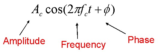
Modulation is the process of converting data or baseband signals into electrical signals optimized for transmission. Modulation, in general, is achieved by varying some characteristic of a periodic waveform, called the carrier signal, in accordance with another separate signal called the modulation signal that typically contains information to be transmitted.
A sinusoid has just three features that can be used to distinguish it from other sinusoids-phase, frequency, and amplitude. For the purpose of radio transmission, modulation is defined as the process whereby the phase, frequency, or amplitude of a radio frequency (RF) carrier wave is varied in accordance with the information to be transmitted.
Noise
Noise poses a significant challenge in satellite communications, comprising unwanted signals that interfere with the desired carrier wave. These unwanted contributions originate from various sources, including natural sources of radiation within the antenna reception area and internal noise generated by components in the receiving equipment. Additionally, noise from carriers transmitted by other sources, not intended for reception, also contributes to interference. Such interference diminishes the receiver’s ability to accurately reproduce the information carried by the desired carrier.
A prevalent model for noise characterization is white noise, characterized by a constant power spectral density across the relevant frequency band. Harmful noise power is that which occurs in the bandwidth B of the wanted modulated carrier. A popular noise model is that of white noise, for which the power spectral density N0 is constant in the frequency band involved. The equivalent noise power N (W) captured by a receiver with equivalent noise bandwidth BN, usually matched to B, is given by N = N0 * BN. This analysis helps in evaluating the noise-related challenges in satellite communications and devising strategies to mitigate their effects on signal integrity and system performance.
Analog Modulation:
In analog modulation an analog modulation signal is impressed on the carrier. Examples are amplitude modulation (AM) in which the amplitude (strength) of the carrier wave is varied by the modulation signal, and frequency modulation (FM) in which the frequency of the carrier wave is varied by the modulation signal. These were the earliest types of modulation, and are used to transmit an audio signal representing sound, in AM and FM radio broadcasting.
FM, in particular, has been widely employed due to its convenience in single-carrier transponder setups, where constant envelope signals allow power amplifiers to operate efficiently at saturation levels, maximizing power utilization.
Modulation can be divided into single carrier modulation, by which the carrier occupies the entire bandwidth (i.e. amplitude, frequency, and phase), and a multicarrier scheme that modulates and transmits different data on multiple carriers. In addition, there is a pulse modulation technique used to change the pulse width and spread spectrum method that spreads the signal energy over a wide band.
Digital Modulation:
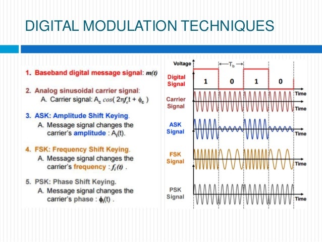
Digital communication systems have emerged as the cornerstone of modern telecommunications, leveraging advanced modulation techniques to transmit digital signals over various mediums. Unlike traditional analog modulation, digital modulation impresses a digital signal, typically represented as a sequence of binary digits (bits), onto the carrier wave. In these systems, parameters of the carrier wave, such as phase, frequency, or amplitude, are manipulated in accordance with the information signals to be transmitted.
Various modulation techniques such as Phase-Shift Keying (PSK), Frequency-Shift Keying (FSK), and Quadrature Amplitude Modulation (QAM) are employed, each offering unique advantages in terms of spectral efficiency, resistance to noise, and data throughput.
In the general M-ary signaling case, the processor accepts k source bits at a time and instructs the modulator to produce one of an available set of M = 2 **k waveform types for T seconds, the symbol period. A digital waveform is taken to mean a voltage or current waveform
representing a digital symbol. This k number of bits comprises the symbol that is represented by the particular phase, frequency, or amplitude.
In practice, M is usually a nonzero power of two (2,4,8,1.6..,). Binary modulation, where k = 1, is just a special case of M-ary modulation. Since the M symbols can be represented by k = log2M binary digits (bits), the data rate can be expressed as R = ( l / T ) log2M = k/T b/s. At various points along the signal route, noise corrupts the waveform s( t) so that its reception must be termed an estimate s(t).
For more information on Satellite Communication Systems and technologies, Please visit
Digital Satellite Comunications
Modern satellite communication has become predominantly digital communications because of the ever-growing demand for data communication, and because digital transmission offers data processing options and flexibilities not available with analog transmission.
A modulator is a device or circuit that performs modulation. A demodulator (sometimes detector) is a circuit that performs demodulation, the inverse of modulation. A modem (from modulator-demodulator) can perform both operations. The frequency band occupied by the modulation signal is called the baseband, while the higher frequency band occupied by the modulated carrier is called the passband.
While the transmitter, consists of a frequency up-conversion stage, a high-power amplifier, and antenna, the receiver portion is occupied by an antenna, a low-noise front-end amplifier, and a down-converter stage, typically to an intermediate frequency (IF).
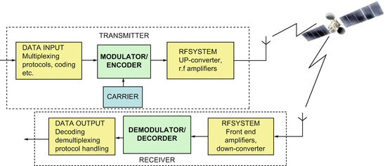
Digital communication systems can have other optional signal processing steps. Source encoding, as defined here, removes information redundancy and performs analog-to-digital (A/D) conversion. Encryption prevents unauthorized users from understanding messages and from injecting false messages into the system. Channel coding can, for a given data rate, improve the error (PE) performance at the expense of power or bandwidth, reduce the system bandwidth requirement at the expense of power or PE performance, or reduce the power requirement at the expense of bandwidth or PE performance.
Frequency spreading renders the signal less vulnerable to interference (both natural and intentional) and can be used to afford privacy to the communicators. Multiplexing and multiple access combine signals that might have different characteristics or originate from different, sources.
Advanced Modulation Techniques
Satellite communication systems face the imperative of meeting escalating demands for rapid data throughput, prompting the adoption of high-order modulation schemes to enhance spectral efficiency.
Higher-Order Modulation: The adoption of higher-order modulation schemes, such as 64-QAM, 256-QAM, and even 1024-QAM, is a significant trend in satellite communications. These schemes allow for higher data rates by encoding more bits per symbol. However, they also require higher signal-to-noise ratios (SNR) and more sophisticated error correction techniques.
However, inherent channel impairments in satellite transmissions, such as extensive path losses, propagation delays, and Doppler shifts, present formidable obstacles to achieving optimal network performance. Consequently, modulation techniques in satellite communications must not only facilitate faster data rates but also mitigate the adverse effects of these channel impairments.
In satellite transmission, RF power amplifiers often operate at compression levels to maximize conversion efficiency, inducing AM/AM and AM/PM distortion. This distortion result in outer points of the I/Q constellation exhibit elevated output power levels due to saturation in the RF power amplifier. Hence, nonlinear amplifiers necessitate modulation schemes resilient to such distortion. Moreover, the amplified output power contributes to heightened noise levels in the signal, underscoring the importance of addressing signal integrity challenges in satellite communication systems
Nonconstant envelope digital modulation schemes
Nonconstant envelope digital modulation schemes, like Quadrature Amplitude Modulation (QAM), dynamically adjust both phase and amplitude to enhance spectral efficiency. Quadrature amplitude modulation (QAM) is particularly noteworthy, where an in-phase signal (I) and a quadrature-phase signal (Q) are modulated with a finite number of amplitudes and then combined. This approach essentially creates a two-channel system, with each channel utilizing ASK principles. The resulting signal represents a fusion of PSK and ASK functionalities, showcasing the versatility of QAM in digital communication.
The constellation diagram of 16PSK and 16QAM demonstrates how 16QAM strategically increases the spacing between constellation points, offering superior resistance to signal impairments. However, it’s worth noting that 16QAM expands the amplitude levels to three rings compared to 16PSK, necessitating a wider linear range for RF power amplifiers to accommodate nonconstant modulation schemes effectively.
In satellite communication, equipment must efficiently transmit at high power levels while preserving output linearity. Although higher modulation schemes facilitate increased data throughput, they concurrently heighten sensitivity to signal impairments. To address these challenges, sophisticated digital modulation techniques, such as Orthogonal Frequency Division Multiplexing (OFDM), come into play. OFDM, utilized in WiFi networks, digital radio stations, and digital cable television transmission, leverages multiple carriers to optimize spectral efficiency and mitigate the impact of signal distortions.
Constant envelope digital modulation schemes
Constant envelope digital modulation schemes, like Frequency Shift Keying (FSK) and Phase Shift Keying (PSK), are widely regarded as optimal for satellite communications due to their ability to mitigate the impact of nonlinear amplification in high-power amplifiers such as Travelling Wave Tube Amplifiers (TWTAs) or Klystron Tube Amplifiers (KTAs).
Among these schemes, PSK stands out as particularly well-suited for satellite links. PSK maintains a constant envelope while offering superior spectral efficiency compared to FSK. In a PSK system, the envelope remains constant, with phase changes occurring discontinuously from symbol to symbol.
In M-ary PSK modulation, different variations accommodate varying numbers of bits per symbol. Binary Phase Shift Keying (BPSK), for instance, represents the simplest form with two states, enabling straightforward demodulation processes. Quadrature Phase Shift Keying (QPSK) defines four states by grouping two consecutive bits to form a symbol. While higher-order PSK, such as 8PSK, achieves increased spectral efficiency with more bits per symbol, it requires greater energy per bit to maintain a consistent Bit Error Rate (BER) at the demodulator output.

Constellation diagrams, as depicted in Figure, illustrate the transmission characteristics of these schemes. Binary PSK (BPSK), Quadrature PSK (QPSK), and 8PSK transmit 1, 2, and 3 bits per symbol, respectively. Higher-order PSK schemes exhibit constellation points closer to each other, making the system more sensitive to channel impairments. Conversely, 4FSK offers higher spectral efficiency compared to 2FSK, although smaller frequency deviations can adversely affect receiver sensitivity.
Satellite communications rely on amplitude phase-shift keying (APSK) modulation to counteract nonlinear distortion. As depicted in the constellation diagram comparing APSK with QAM schemes, APSK arranges its states in rings, ensuring consistent amplitude compression within each ring. For instance, while a 16APSK constellation features two amplitudes (rings), a comparable 16QAM constellation displays three. Similarly, a 32APSK constellation presents three amplitudes versus five in 32QAM. The varying amplitude levels in APSK result in closer proximity of the rings, posing challenges for compensating nonlinearities.

APSK modulation offers flexibility through adjustable parameters like the number of rings, symbols per ring, and ring spacing. Designers can optimize these parameters to strike a balance between minimizing peak-to-average power ratio (PAPR) and enhancing distortion resistance.
In QPSK modulation, the voltages which modulate the two carriers in quadrature change simultaneously, and the carrier can be subjected to a phase change of 180. In a satellite link that includes filters, large phase shifts cause amplitude modulation of the carrier. The non-linearity of the channel transforms these amplitude variations into phase variations that degrade the performance of the demodulator. Several variants of QPSK modulation have been proposed to limit the amplitude of the phase shift.
Two digital modulation schemes of special interest for use on nonlinear bandlimited channels are called staggered (or offset) quadraphase PSK (SQPSK or OQPSK), and minimum shift keying (MSK). Both techniques retain low spectral sidelobe levels while allowing’ efficient detection performance.
With offset QPSK (OQPSK), also called staggered QPSK (SQPSK), the Ik and Qk modulating bit streams are offset by half a symbol duration, i.e. Ts=2 ¼ Tc, the duration of a bit. The phase of the carrier changes every bit period but only +- 90 or 0. This avoids the possible 180 phase shift associated with the simultaneous change in the two bits in the modulating dibit with QPSK. It results in a reduced envelope variation when the modulated carrier is filtered.
OQPSK uses rectangular pulse shapes, and MSK uses half-cycle sinusoid pulse shapes. Because of the sinusoidal pulse shaping in MSK, it can be viewed as continuous-phase FSK with a frequency deviation equal to one-half the bit rate.
For nonorthogonal schemes, such as MPSK signaling, one often uses a binary-to-M-ary code such that binary sequences corresponding to adjacent symbols (phase shifts) differ in only one bit position; one such code is the Gray code. When a M-ary symbol error occurs, it is more likely that only one of the k input bits will be in error. Ps = PE/k (for PE << 1) . For convenience, this discussion is restricted to BPSK (k=1, M = 2) modulation. For the binary case, the symbol error probability equals the bit error probability.
Adaptive Modulation and Coding (AMC): AMC dynamically adjusts the modulation and coding scheme based on real-time channel conditions. This approach optimizes throughput and reliability by selecting the best modulation scheme for the current SNR, thus improving the overall efficiency of the satellite link.
2. Spectrally Efficient Modulation
Carrier Aggregation: Carrier aggregation combines multiple carrier frequencies to increase the overall bandwidth and data rate. This technique is particularly useful for leveraging fragmented spectrum and improving the capacity of satellite communication systems.
Orthogonal Frequency Division Multiplexing (OFDM):
OFDM divides the available bandwidth into multiple orthogonal subcarriers, each modulated with a low-rate data stream. This technique is highly resistant to multipath fading and intersymbol interference (ISI), making it ideal for satellite communications. OFDM is also used in conjunction with advanced error correction and adaptive modulation techniques to maximize spectral efficiency.
Orthogonal Frequency-Division Multiplexing (OFDM) stands out as a digital multi-carrier technique offering numerous advantages over single-carrier methods. Widely adopted across various broadband wireless communication standards like 4G/5G, Wi-Fi, and digital video broadcast for both terrestrial and satellite systems, OFDM utilizes multiple closely spaced orthogonal subcarrier signals to transmit data concurrently. This approach boasts superior spectral efficiency compared to traditional digital modulation schemes such as QAM and PSK, along with robustness against channel linear distortion.
OFDM’s efficacy lies in its utilization of numerous orthogonal subcarriers, each carrying data independently. This orthogonal arrangement ensures minimal interference between subcarriers, optimizing spectrum utilization. However, OFDM signals typically exhibit a higher Peak-to-Average Power Ratio (PAPR) compared to traditional modulation schemes, necessitating a considerable back off to prevent compression at high output power levels. Nonlinear effects induced by high-power amplifiers can exacerbate distortions in satellite systems, potentially leading to system failures. Therefore, accurate characterization of distortion performance in satellite RF components is critical for robust system design.
Trellis Coded Modulation (TCM)
Trellis Coded Modulation (TCM) merges modulation and encoding processes to enhance efficiency without increasing bandwidth. Particularly valuable for bandwidth-constrained channels, TCM optimizes data transmission efficiency by leveraging multilevel phase modulation techniques such as Phase Shift Keying (PSK), Phase Amplitude Modulation (PAM), or Quadrature Amplitude Modulation (QAM). By applying TCM, performance gains can be achieved without widening the signal bandwidth. For instance, transitioning from four to eight signal phases requires approximately 4dB additional signal power to maintain the same error rate. TCM, when integrated with encoding processes, significantly boosts coding gain while overcoming signal set expansion challenges.
3. Error Correction and Signal Processing
Low-Density Parity-Check (LDPC) Codes: LDPC codes are a class of error-correcting codes that provide near-Shannon-limit performance. They are widely used in modern satellite communication standards, such as DVB-S2X, to enhance the robustness and efficiency of the transmission.
Turbo Codes: Turbo codes are another powerful error-correcting technique that combines two or more convolutional codes with an interleaver to achieve high error correction performance. They are particularly effective in scenarios with low SNR.
Modulation Schemes Analysis
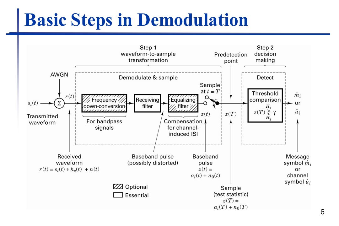
The key feature of a digital communications system (DCS) is that it sends only a finite set of messages, in contrast to an analog communications system, which can send an infinite set of messages. In a DCS, the objective at the receiver is not to reproduce a waveform with precision; it is instead to determine from a noise-perturbed signal which of the finite set of waveforms had been sent by the transmitter. An important measure of system performance is the average number of erroneous decisions made or the probability of error (PE).
When the receiver exploits knowledge of the carrier wave’s phase reference to detect the signals, the process is called coherent detection; when it does not have phase reference information, the process is called noncoherent. In ideal coherent detection, prototypes of the possible arriving signals are available at the receiver. These prototype waveforms exactly replicate the signal set in every respect, even RF phase. The receiver is then said to be phase-locked to the transmitter.
For coherent detection, product integrators (or their equivalents) are used During detection, the receiver multiplies and integrates (correlates) the incoming signal with each of its prototype replicas. Noncoherent modulation refers to systems designed to operate with no knowledge of phase; phase estimation processing is not required. Reduced complexity is the advantage over coherent systems, and increased PE is the trade-off.
For coherent detection, product integrators (or their equivalents) are used; for noncoherent detection, this practice is generally inadequate because the output of a product integrator is a function of the unknown phase angle. However, if we assume that phase varies slowly enough to be considered constant over two, period times (ZT), the relative phase difference between two successive waveforms is independent of phase angle.
The analysis of all coherent demodulation or detection schemes involves the concept of distance between an unknown received waveform and a set of known waveforms. Since any arbitrary waveform set, as well as noise, can be represented as a linear combination of orthonormal waveforms, we can use Euclidean-like distance in such an orthonormal space, as a decision criterion for the detection of any signal set in the presence of AWGN. The vector or point n is a random vector; hence, r is also a random vector. For example in binary modulation type, the detector’s task after receiving signal r is to decide which of the signal sl or s2 was actually transmitted. The decision stage must decide which signal was transmitted by measuring its location within the signal space.
The method is usually to decide upon the signal classification that yields the minimum PE, although other strategies are possible. The noise is modeled as a random process with zero mean and a Gaussian distribution. For the case where M equals two signal classes, with S I and s2 being equally likely and the noise being AWGN, the minimum-error decision rule turns out to be Choose the signal class such whose distance or norm from the received signal is minimum.
Symbol detection in a realizable system, even in the absence of noise, suffers from intersymbol interference, ISI; the tail of one pulse spills over into adjacent symbol intervals so as to interfere with correct detection: Nyquist showed that the theoretical minimum bandwidth needed to transmit x symbols per second (Symbols/s) without ISI is x / 2 Hz; this is a basic theoretical constraint, limiting the designer’s goal to expend as little bandwidth as possible. In practice, it typically requires x Hz bandwidth for the transmission of x symbols/s.
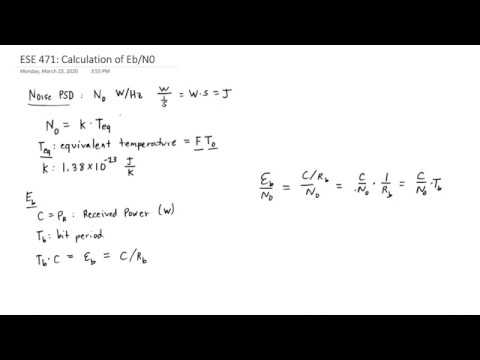
(Energy per bit )Eb/No (Noise Density) = (Signal Power) S / N(Noise Power) X (Signal Bandwidth) W/R (Data Rate)
The dimensionless ratio Eb/No (required to achieve a specified Pa), is uniformly used for characterizing digital communications system performance. Therefore, required Eb /No can be considered a metric that characterizes the performance of one system versus another; the smaller the required Eb/No, the more efficient the system modulation and detection process.

At large SNRs, it can be seen that there is approximately a 4-dB difference between the best (coherent PSK) and the worst (noncoherent FSK).In some cases, 4 dB is a small price to pay for the implementation simplicity gained in going from a coherent PSK to a noncoherent FSK; however, for some applications, even a 1-dB saving is worthwhile. There are other considerations besides PB and system complexity; for example, in some cases (such as randomly fading propagation conditions), a noncoherent system is more robust and desirable because there may be difficulty in establishing a coherent reference.
Notice also that the location of the MPSK points indicates that BPSK (M = 2) and QPSK (M = 4) require the same Eb/No. That is, for the same value of Eb/No QPSK has a bandwidth efficiency of 2 b/s/Hz, compared to 1 b/s/Hz for BPSK. This unique feature stems from the fact that QPSK is effectively a composite of two BPSK signals, transmitted on waveforms orthogonal to one another and having the same spectral occupancy. Each of the two orthogonal BPSK signals comprising QPSK yields half the bit rate and half the signal power of the QPSK signal; hence the required Eb/No for a given PB is identical for BPSK and QPSK.
In case of DPSK modulation, the carrier phase of the previous signaling interval is used as a phase reference for demodulation. Its use requires differential encoding of the message sequence at the transmitter since the information is carried by the difference in phase between two successive waveforms.
One way of viewing the difference between coherent PSK and DPSK is that the former compares the received signal with a clean reference wherein the latter however two noisy signals are compared with each other. Thus, we might say there is twice as much noise in DPSK as in PSK. Consequently, DPSK manifests a degradation of approximately 3 dB when compared with PSK; this number decreases rapidly with increasing signal-to-noise ratio. In general, the errors tend to propagate (to adjacent period times) due to the correlation between signaling waveforms. The trade-off for this performance loss is reduced system complexity.
System Tradeoffs
System trade-offs are fundamental a to the digital communications designs. The goals of the designer are: (1) to maximize transmission bit rate R, (2) to minimize the probability of bit error PB, (3) to minimize required power, or relatedly, to minimize required bit energy per noise density Eb/No, (4) to minimize required system bandwidth W, (5) to maximize system utilization, that is, to provide reliable service for a maximum number of users, with minimum delay and maximum resistance to interference, and (6) to minimize system complexity, computational load, and system cost.
The designer usually seeks to achieve all these goals. However, goals (1) and( 2) are clearly in conflict with goals (3) and (4); they call for simultaneously maximizing R, while minimizing PB, Eb/No, and W. There are several constraints and theoretical limitations that necessitate the trading-off of any one requirement with each of the others. Some of the constraints are: the Nyquist theoretical minimum bandwidth requirement, the Shannon-Hartley capacity theorem, the Shannon limit, government regulations (for example, frequency allocations), technological limitations (for example, state-of-the-art components), and other system requirements (for example, satellite orbits).
Capacity relationship (Shannon-Hartley theorem)
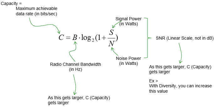
It is possible to transmit information over such a channel at a rate R, where R < C, with an arbitrarily small error rate by using a sufficiently complicated coding scheme. For a rate R > C, it is not possible to find a code which can achieve an arbitrarily small error rate.
The ordinate R/W is a measure of how much data can be transmitted in a specified bandwidth within a given time therefore reflects how efficiently the bandwidth resource is utilized. The abscissa is Eb/No in decibels. Notice that for MPSK modulation, R/W increases with increasing M; however, for MFSK modulation, R/W. decreases with increasing M.
For orthogonal signal sets, such as FSK modulation, M-ary signaling, compared to binary, can provide an improved Ps performance or a reduced Eb/No requirement, at the cost of an increased bandwidth requirement. For non-orthogonal signal sets, such as multiphase shift keyin(gM PSK) modulation, M-ary signaling, compared to binary, can provide a reduced bandwidth requirement, at the cost of a degraded-PB performance or an increased &,/No requirement.
Once modulation, coding scheme, and available Eb/No are chosen, system operation is characterized by a particular point in the error-rate plane. Possible trade-offs can be viewed as changes in the operating point on one of the curves, or as changes in the operating point from one curve to another curve of the family.
We are not as free to make trade-offs as we might like; Government regulations dictate the choice of frequencies, bandwidths, transmission power levels, and-in the case of satellites, orbit selection. The satellite orbit and geometry of coverage fixes the satellite antenna gain. Technological state-of-the-art constrains such items as satellite power transmission and earth station antenna gain. There may be other system requirements (for example, the need to operate under scintillation or interference conditions) that can influence the choice of modulation and coding.
Modulation Measurements
Error Vector Magnitude (EVM) measurements offer a straightforward and quantitative assessment of digital modulation signals. EVM represents the Root Mean Square (RMS) of error vectors, expressed as a percentage relative to the EVM Normalization Reference. These error vectors originate from the detected point of the I/Q reference signal vector to the I/Q measured-signal vector.
In the equations below, n denotes the symbol index, while N represents the total number of symbols. Ierr and Qerr signify the errors in the in-phase and quadrature components, respectively, calculated as the differences between the reference (Ref) and measured (Meas) values.
Errors may stem from various sources, including phase noise from local oscillators, power amplifier noise, and I/Q modulator impairments. EVM serves as a vital metric for assessing the modulation quality of vector signal generators. For instance, a high-performance signal generator can achieve EVM levels as low as 0.4% for a 160 MHz 802.11ac signal. Such low EVM performance offers ample test margin for receiver sensitivity evaluations and component characteristics assessments.
EVM (dB) = 20 log10 (EVM (%))
Emerging Trends
1. Software-Defined Radio (SDR)
SDR technology allows the implementation of digital modulation schemes in software rather than hardware. This flexibility enables rapid prototyping and deployment of new modulation techniques and standards. SDRs are crucial for adapting to the dynamic requirements of modern satellite communications, such as the need for interoperability and future-proofing.
2. Machine Learning and AI
Machine learning (ML) and artificial intelligence (AI) are being integrated into satellite communication systems to optimize modulation and coding schemes. AI algorithms can predict channel conditions and adjust modulation parameters in real-time, enhancing the performance and reliability of satellite links.
3. Quantum Communications
Quantum communications represent a frontier technology with the potential to revolutionize satellite communications. Quantum key distribution (QKD) ensures ultra-secure communication by leveraging the principles of quantum mechanics. While still in the experimental stage, QKD via satellite is an area of active research and development.
Conclusion
The field of digital modulation for satellite communications is evolving rapidly, driven by the need for higher data rates, better spectral efficiency, and more robust error correction.
Most communications systems optimize efficiencies in system designs, including spectral, power, and cost. The selection of modulation schemes for satellite communications depends on the communication channels, hardware limitations, and data throughput requirements. Also, both custom APSK and OFDM modulation schemes bring in test challenges – generating and analyzing custom, proprietary modulation schemes.
Advanced modulation techniques, adaptive schemes, and cutting-edge technologies like SDR and AI are transforming how satellite communications are designed and implemented. As these trends continue to develop, they promise to deliver more efficient, reliable, and versatile satellite communication systems, meeting the ever-growing demands of global connectivity.
References and Resources also include:
https://blogs.keysight.com/blogs/tech/rfmw.entry.html/2020/08/24/modulation_schemesf-6MpZ.html