Home / Technology / Electronics & EW / Satellite Antenna Control Systems: Optimizing Tracking for Reliable Communication

Satellite Antenna Control Systems: Optimizing Tracking for Reliable Communication

In our interconnected world, satellite communications are crucial for various applications, including global navigation, weather forecasting, internet connectivity, and defense operations. The backbone of these communications is the satellite antenna control system, which ensures precise tracking and robust signal transmission between ground stations and satellites.

Unlike fixed terrestrial communication towers, satellite antennas on Earth stations must constantly track moving targets – satellites orbiting thousands of kilometers above the Earth. These satellites zip around the planet at high speeds, making it crucial for the antenna to maintain a precise line of sight to ensure optimal signal reception and transmission.

Key Components of Satellite Communication Systems

Satellite communication systems comprise two main segments: the space segment and the ground segment.

The Space Segment

The space segment consists of the satellites themselves. These artificial satellites relay and amplify radio telecommunications signals via transponders, creating communication channels between transmitters and receivers at different locations on Earth.

The Ground Segment

The ground segment encompasses the ground stations that coordinate communication with the satellites. Ground stations are equipped with antennas, tracking systems, and transmitting and receiving equipment necessary for maintaining a reliable link with satellites.

The Mechanics of Satellite Communication

Satellite communication systems consist of two main segments, the space segment and the earth or ground station. The ground station system coordinates the communication process with satellites in space. A communications satellite is an artificial satellite that relays and amplifies radio telecommunications signals via a transponder; it creates a communication channel between a source transmitter and a receiver at different locations on Earth.

Satellite communications involve four steps: An uplink Earth station or other ground equipment transmits the desired signal to the satellite; The satellite amplifies the incoming signal and changes the frequency; The satellite transmits the signal back to Earth, and The ground equipment receives the signal.

Satellite communications systems use various frequencies for signal propagation depending on the purpose, nature, and regulations in the region of operation. Examples of frequency bands are Very High Frequency (VHF) ranging from 30 to 300MHz, Ultra High Frequency (UHF) ranging from 0.3 to 1.12GHz, L-band ranging from 1.12-2.6 GHz, S-band ranging from 2.6 to 3.95 GHz, C-band ranging from 3.95 to 8.2 GHz, X-band ranging from 8.2 to 12.4 GHz, Ku- band ranging from 12.4 to 18 GHz, K- band ranging from 18.0 to 26.5 and Ka-band ranging from 26.5 to 40 GHz. However, communications above 60 GHz are generally challenging because of the high power needed and equipment cost.

Satellite Communication Networks

Satellite communications networks consist of user terminals, satellites, and a ground network that provides control and interface functions.

Geostationary satellite networks utilize a smaller number of satellites, and each satellite provides satellite coverage to a fixed area of the Earth. Geostationary satellites are generally located above the equator and follow the Earth’s orbit which means each Geostationary satellite stays in the same place relative to the Earth’s surface. Geostationary satellites generally have superior data bandwidth, but since the satellites are around 36,000 km above the Earth will experience greater latency or voice delay than LEO satellites.

Low Earth Orbit (LEO) satellite networks are made up of a constellation of small satellites that orbit the Earth in a series of planes. The orbiting pattern of LEO satellite networks means that the individual satellites in the constellation are continually moving relative to the Earth’s surface. LEO satellite networks are well suited to mobile applications, where you need to use the service while on the move.

LEO satellites are also much closer to the Earth (800-1,400 km) than Geostationary satellites (approximately 36,000 km), so latency or voice delay in the network can be considerably less. Pivotel products that use LEO satellite networks include all Iridium, inReach, SPOT and Globalstar satellite solutions.

The Role of Ground Stations

Satellite Ground Station

Ground stations are essential for satellite tracking, control, and communication. They handle telemetry, tracking, and command (T&C) services and allocate satellite resources to ensure efficient operation. Ground station consists of an antenna subsystem, with an associated tracking system, a transmitting section and a receiving section. It includes an antenna system for the transmission and reception of signals. Low noise block down converter, High Power Amplifier (HPA) transmitter with power from a few watts to hundred kilowatts depending on capacity and regulations, Up and Down converters, modem, encoders, multiplexers, control and tracking systems, interfaces for user terminals.

  • Antenna Subsystems: For signal transmission and reception.
  • Tracking Systems: To keep antennas pointed towards satellites.
  • Transmitting and Receiving Sections: Including high-power amplifiers, low noise block down converters, up and down converters, modems, encoders, and multiplexers.

The antenna is generally common to transmission and reception for reasons of cost and bulk. Separation of transmission and reception is achieved by means of a diplexer. The tracking system keeps the antenna pointing in the direction of the satellite in spite of the relative movement of the satellite and the station.

The node configuration depends on the size and required services. It ranges from large ground station use as gateways in a telecommunication network to Very Small Aperture Terminals (VSAT) that deliver data communication applications to remote region.

Ground station antennas vary in size and function, tailored to specific needs:

  1. Large Antennas: Used for global networks like INTELSAT, with gains of 60 to 65 dBi and diameters ranging from 15 to 30 meters.
  2. Medium-Sized Antennas: For data receive-only terminals, typically 3 to 7 meters in diameter.
  3. Small Antennas: For direct broadcast reception, 0.5 to 2 meters in diameter.

Antenna Specifications

Key characteristics required for Earth station antennas include:

  • High Directivity: Ensuring the antenna focuses on the nominal satellite position.
  • Low Directivity Elsewhere: Minimizing interference with nearby satellites.
  • High Efficiency: Maximizing performance for both uplink and downlink frequency bands.
  • High Polarization Isolation: Enabling efficient frequency reuse through orthogonal polarization.
  • Low Noise Temperature: Reducing interference from environmental noise.
  • Accurate Pointing: Continuously targeting the satellite despite relative movement.
  • Weather Resilience: Maintaining performance in various meteorological conditions.

The antenna gain directly impacts the effective isotropic radiated power (EIRP) and the figure of merit (G/T) of the station. Beamwidth determines the type of tracking system suitable for the satellite’s orbit

The figure of merit (G/T) of Earth station  is defined at the station receiver input as the ratio of the composite receiving gain G to the system noise temperature T of the earth station. The gain of an antenna  is maximum in the direction of maximum radiation (the electromagnetic axis of the antenna, also called the boresight) therefore it is necessary to point the antenna such that the satellite is on its foresight.

Large earth station antennas are expensive to construct and to maintain so that there is a premium in obtaining the maximum efficiency from the system.  Typical values are 40.7dBK−1 for an INTELSAT A, 30 metre diameter antenna operating at 4/6GHz

The minimum receivable signal level is set by inherent noise in the system. Earth stations are required to detect small signals so the control of the noise parameters is important. . For an earth station, the noise acquired by the antenna originates from the sky and surrounding ground radiation. It depends on the frequency, the elevation angle and the atmospheric conditions (clear sky or rain). The system noise temperature T is a function of the antenna noise temperature TA, the feeder losses LFRX, the thermodynamic temperature TF of this feeder and the effective noise temperature TeRX of the receiver.

The antenna system is central to ground station operations, often using a diplexer to separate transmission and reception. Accurate pointing and tracking are crucial for maintaining a strong communication link.

Mountings for Antenna Pointing and Tracking

To ensure accurate pointing and tracking of satellite signals, various mounting systems for antennas are employed. Each type has its unique advantages and limitations based on the specific requirements of the satellite mission.

Azimuth-Elevation Mounting

Azimuth-Elevation (Az-El) Mounting: This is the most commonly used mounting system for steerable Earth station antennas. It features:

  • Primary Axis (Vertical): Allows adjustment of the azimuth angle (A) by rotating the antenna support around this axis.
  • Secondary Axis (Horizontal): Allows adjustment of the elevation angle (E) by rotating the antenna around this horizontal axis.

Advantages:

  • Widely used and well understood.
  • Simplifies the tracking process for most satellite paths.

Disadvantages:

  • High angular velocities are required when tracking a satellite near the zenith. The elevation angle reaches 90°, leading to a mechanical stop to prevent overtravel.
  • To continue tracking, the antenna must perform a rapid 180° rotation about the primary axis, which can be mechanically challenging and increases wear and tear.

X-Y Mounting

X-Y Mounting: This mounting system has a fixed horizontal primary axis and a secondary axis orthogonal to the primary axis.

  • Primary Axis (Horizontal): Fixed in position.
  • Secondary Axis (Orthogonal): Rotates about the primary axis.

Advantages:

  • Avoids the high-speed rotation required in Az-El mounting when tracking satellites passing through the zenith.
  • Particularly useful for low Earth orbit (LEO) satellites and mobile stations.

Disadvantages:

  • Less suitable for geostationary satellites due to its complexity and the nature of the satellite orbits.

Polar or Equatorial Mounting

Polar or Equatorial Mounting: This system aligns the primary axis (hour axis) parallel to the Earth’s rotational axis and the secondary axis (declination axis) perpendicular to it.

  • Primary Axis (Hour Axis): Parallel to the Earth’s axis of rotation, allowing compensation for Earth’s rotation by rotating about this axis.
  • Secondary Axis (Declination Axis): Perpendicular to the primary axis, allowing adjustments in declination.

Advantages:

  • Ideal for astronomical telescopes and tracking the apparent movement of stars with minimal adjustments.
  • Useful for geostationary satellite links as it allows pointing at multiple satellites by rotating about the hour axis.
  • Simplifies tracking of geostationary satellites by compensating for Earth’s rotation.

Disadvantages:

  • Requires slight adjustments about the declination axis due to satellites not being at infinity.
  • More complex to set up compared to Az-El mounting.

Each mounting system has specific applications where it excels. Azimuth-elevation mounting is versatile and widely used, but requires rapid movements near the zenith. X-Y mounting eliminates zenith-related issues, making it suitable for LEO satellites and mobile stations. Polar mounting is ideal for geostationary satellites and astronomical applications, providing smooth tracking by compensating for Earth’s rotation. Understanding these systems helps in selecting the appropriate mounting based on the satellite mission and operational requirements.

Antenna Tracking

Tracking consists of maintaining the axis of the antenna beam in the direction of the satellite in spite of the movement of the satellite or station. Even in the case of a geostationary satellite, orbital perturbations cause apparent displacements of the satellite which are, however, limited to the ‘station-keeping box’. Furthermore, the station can be installed on a mobile vehicle, the location, and direction of which vary with time.

The performance required of the tracking system varies in accordance with the characteristics of the antenna beam and the satellite orbit. For small antennas, the tracking system can be eliminated (fixed mounting) and this enables costs to be reduced.

Several types of tracking are possible and are characterized by their tracking error (pointing angle error). Choice of the type of tracking depends on the antenna beamwidth and the magnitude of the apparent movement of the satellite.  Decisions relating to antenna installation and tracking procedure depend on the beamwidth in relation to the magnitude of apparent movement of the satellite; the determining criterion is the variation of antenna gain with depointing.

Another antenna characteristic that is associated with its diameter and directly affects the performance of orientating devices is its mass. For small antennas, the mass of the parabolic reflector ranges from a few tens to several hundreds of kilograms. For large antennas, it is several tons.

Programmed Tracking

Programmed tracking achieves antenna pointing by supplying the control system with azimuth and elevation angles corresponding to each instant. This process operates in an open-loop manner, meaning it does not determine the pointing error between the actual direction of the satellite and the intended aiming direction at each moment.

Applications:

  • Earth Station Antennas with Large Beamwidth: Suitable when high pointing accuracy is not crucial.
  • Non-Geostationary Satellites: Used to pre-position the antenna to ensure acquisition by a closed-loop tracking system operating on the satellite beacon when high pointing accuracy is necessary.

Computed Tracking

Computed tracking is a variant of programmed tracking, designed for geostationary satellites. This method incorporates a computer to evaluate antenna orientation control parameters using orbital parameters such as inclination, semi-major axis, eccentricity, right ascension of the ascending node, argument of the perigee, and anomaly.

Applications:

  • Intermediate Beamwidth Antennas: Ideal when beamwidth does not justify closed-loop beacon tracking.
  • Orbit Parameter Updates: The system periodically refreshes data (every few days) and can extrapolate the progression of orbit parameters from stored daily satellite displacements.

Closed-Loop Automatic Tracking

Closed-loop automatic tracking is essential for antennas with a small angular beamwidth relative to the satellite’s apparent movement. It continuously aligns the antenna with a satellite beacon to achieve precise tracking.

Advantages:

  • High Accuracy: Tracking error can be less than 0.005 degrees with a monopulse system.
  • Autonomy: Does not rely on ground-sourced tracking information.
  • Mobile Stations: Vital for mobile stations where antenna movement cannot be predetermined.

Techniques:

  1. Sequential Amplitude Detection:
    • Conical Scanning, Step-by-Step Tracking, and Electronic Tracking: These methods utilize variations in received signal levels to determine the direction of maximum gain.
    • Step-by-Step Tracking: Also known as step-track or hill-climbing, it involves successive displacements to maximize the received beacon signal.
  2. Electronic Tracking:
    • Comparison to Step-by-Step: Similar in approach but uses electronic displacement of the beam in four cardinal directions by varying the impedance of microwave devices.
  3. Monopulse Tracking:
    • Multimode Monopulse: Utilizes higher-order modes in a circular waveguide for tracking.
    • Error Angle Measurement: Obtained by comparing waves from multiple sources or by detecting higher-order modes in a waveguide.

Multimode Monopulse for Low-Earth-Orbit (LEO) Satellites

For LEO satellites, which are visible for a short duration (10-15 minutes), effective communication is critical. Monopulse tracking systems with multiple antennas feeding a reflector system develop azimuth difference, elevation difference, and sum signals to indicate pointing accuracy.

Challenges with Conventional Monopulse Systems:

  • Cumbersome Antenna Arrays: Large and heavy arrays with multiple horns needed for sum and difference signals.

Solution:

  • Monopulse Multimode Tracking Feed: Uses higher-order modes in a circular waveguide, providing efficient tracking without the bulkiness of traditional arrays. This system maximizes the communication signal when aligned with the point source and excites higher-order modes when misaligned, ensuring precise tracking.

Each tracking system has distinct applications based on antenna size, satellite type, and required accuracy. Programmed tracking is straightforward and suitable for broad-beam antennas. Computed tracking balances complexity and accuracy for geostationary satellites. Closed-loop tracking ensures high precision for narrow-beam antennas, especially crucial for mobile and LEO applications. Multimode monopulse tracking addresses the bulk and efficiency issues of conventional systems, making it a valuable innovation for modern satellite communications.

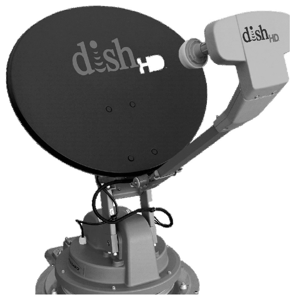
Satellite antenna control system ; key components

  • Antenna: The workhorse of the system, the antenna can be a massive parabolic dish or a phased array antenna. Its design depends on the frequency range of the satellite signal being received or transmitted.
  • Gimbal System: This motorized mount allows the antenna to rotate in two axes (azimuth and elevation) to track the satellite’s movement across the sky. High-precision motors like stepper motors or brushless DC motors ensure smooth and accurate positioning.
  • Control Unit: The brain of the system, the control unit houses a powerful processor that receives real-time data on the satellite’s position (orbital elements) from sources like satellite ephemeris data. It then calculates the necessary antenna pointing angles and transmits control signals to the motors.
  • Tracking Software: This software plays a crucial role in processing the satellite ephemeris data and translating it into precise control commands for the motors. It may also incorporate error correction algorithms to account for factors like wind gusts or mechanical imperfections in the system.

A well-designed satellite antenna control system offers several advantages:

  • Stronger Signals: Precise pointing ensures optimal signal strength, leading to clearer communication, higher data rates, and reduced risk of signal dropouts.
  • Enhanced Tracking Accuracy: Advanced algorithms and high-precision motors enable the system to track even fast-moving satellites with exceptional accuracy.
  • Automatic Operation: The system can operate autonomously, freeing human operators to focus on other tasks.
  • Scalability and Customization: Systems can be designed to handle different antenna sizes, satellite frequencies, and tracking requirements.

Conclusion

Satellite antenna control systems are vital for reliable and efficient satellite communications. By integrating advanced components and employing sophisticated tracking techniques, these systems ensure robust links between ground stations and satellites. As technology advances, we can anticipate even more precise and efficient tracking systems, further enhancing our capabilities in satellite communications and space exploration.


References and Resources also include:

https://www.analogictips.com/a-monopulse-tracking-system-for-satellite-tracking/


About Rajesh Uppal

Check Also

Advancing Stealth: Chinese Scientists Develop Meta-Materials-Based Radar Cloaks

Stealth technology has long been a cornerstone of military innovation, offering the promise of enhanced …

error: Content is protected !!