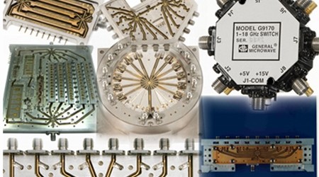
One of the most common functions in all electronic circuitry is switching. Switching has a wide range of uses. Engineers in industries ranging from telecommunications to military/aerospace need high-performance RF/microwave switching as part of their test setups. An RF switch or microwave switch is a device to route high frequency signals through transmission paths. RF (radio frequency) and microwave switches are used extensively in microwave test systems for signal routing between instruments and devices under test (DUT). Incorporating a switch into a switch matrix system enables you to route signals from multiple instruments to single or multiple DUTs. This allows multiple tests to be performed with the same setup, eliminating the need for frequent connects and disconnects. The entire testing process can be automated, increasing the throughput in high-volume production environments.
Switches for RF and microwave applications are fabricated with a number of different device technologies and available with performance levels in a wide range of signal-path configurations. They can be as simple as a single-pole, single-throw (SPST) device to a complex multithrow switch or switch matrix. Selecting an RF switch is a matter of matching its electrical and mechanical characteristics to the needs of the application. RF/microwave switches come in many shapes, sizes, and technologies, from tiny integrated circuits (ICs) to larger, electromechanical switches.
As with many comparisons of different technologies, solid-state and electromechanical switches each have their benefits and their shortcomings. Solid-state switches, which include discrete and IC components that employ PIN diodes and GaAs MESFETs as switching devices, are known for their long operating lifetimes, fast switching times, and small size. Electromechanical switches are larger and heavier, with considerably slower switching times, but boast excellent electrical performance.
The complexity of a switch is a function of the number of signal paths through the component. A relay or switch with a single path is known as a single-pole, single-throw (SPST) component, while a component used, for example, to connect a single antenna to four receivers is a single-throw, four-pole (SP4T) switch. The number of poles and throws will be dictated by the needs of an application. Switches can be designed to be absorptive or impedance matched to the surrounding circuitry when in their “off” state (high-isolation state), through the use of terminating resistors. They can also be configured as reflective short or reflective open when in the high-isolation state.
RF CMOS switches are crucial to modern wireless telecommunication, including wireless networks and mobile communication devices. Infineon’s bulk CMOS RF switches sell over 1 billion units annually, reaching a cumulative 5 billion units, as of 2018
Switching parameters
Switches control signal flows in RF/microwave circuits. They provide signal routing through a number of different configurations and technologies, and are characterized by many different parameters for comparison. Switch electrical performance is characterized by a number of parameters, including its frequency range; the insertion loss when the switch is in the “on” state; the isolation when the switch is in the “off” state; its return loss; its switching speed from on to off or off to on; how well it is impedance matched (its VSWR) for use with associated components; its power-handling capability (usually defined as signal power where the insertion loss increases by 1 dB, or 1-dB compression); its linearity (usually in terms of its second- and/or third-order intercept point); and its durability or reliability, typically specified as the number of expected switching operations. For all their moving parts, for example, it is not unheard of for electromechanical switches to be rated for 100 million or more switching operations with minimal degradation in insertion loss.
At high frequencies, many issues relating to performance of any circuit also apply to switches. The most important are: Loss versus frequency (bandwidth); VSWR versus frequency (mismatch); On-off isolation (feed-through); · Isolation to other circuitry (crosstalk);· Power handling;· Switching speed; and Operating lifetime (reliability, MTTF)
Other basic parameters that are important for specific applications include physical size, operating voltage, power consumption and
rated temperature range. In instrumentation applications, excellent repeatability (consistency of performance from one operation to
the next) is required.
Electromechanical Switches
Electromagnetic switches and relays make use of the magnetic field created by current flow to make or break a switch contact. They are typically comprised of a coil, some form of armature mechanism, and electrical contacts on the armature. When current flows through the coil, the armature moves due to the force of the magnetic field that is formed, and an electrical path is formed through the contact. When current flow ceases, the armature shifts back to its original position, and the electrical contact is broken. By providing adequate contact area, electromechanical switches can be made for high power levels. But as the contact size is increased, the size of the switch or relay also increases. Because of the mechanical motion of the armature, an electromechanical switch is limited in switching and settling time to about typically 5 to 20 ms.
Electromechanical switches and relays are available in latching and nonlatching configurations. A latching switch requires continuous current flow to maintain a closed circuit; once closed, a nonlatching switch continues to maintain electrical connections even without current applied.
Electromechanical switches are most often used for high power, or where the lowest possible loss is required. Both of these requirements are best met with the physical connection of metal-to-metal contacts.
Conventional relays
At frequencies below 500 MHz, it is often possible to use general-purpose relays that are primarily designed for control of AC/DC power.
Certain manufacturing methods unintentionally result in reasonably low capacitance between open contacts, and low inductance in
the internal connection. Although limited to the range from low frequencies through VHF, this part of the spectrum includes many communications and IF applications.
RF optimized relays
These switches are manufactured like general-purpose relays, but with improvements in the internal construction that further enhance RF performance. Most relays in this group are characterized up to 1 GHz, and offer a price/performance choice that fits many applications.
Microwave relays
The above relays types have limitations on some aspects of performance, usually off isolation and crosstalk. To handle switching at higher frequencies, and with higher performance, specially-designed relays are a typical solution. This family of relays might be better described as switches with electrical actuators, since they often bear little resemblance to general-purpose relays. To maintain low VSWR, these devices are designed with short signal paths and a physical structure that mimics either stripline or oaxial line. High isolation is obtained by
grounding the signal path in the off position, perhaps augmented by actuation movement that increases the distance between disconnected contacts, lowering the capacitance. Crosstalk is reduced with shielding between signal paths and ports, often cast or machined into the switch housing
Solid State Switches
Solid state switches are used when switching speed and reliability are key performance issues. They also are low cost and have small
physical size. The combination of low power consumption and small size generally simplifies the design of the surrounding circuitry.
Forward-biased diodes For circuit-level RF switching, a diode biased to full conduction is quite effective. Various technologies—silicon, “hot carrier,” GaAs and others—offer various options for loss, frequency range, and compatibility with the rest of the circuitry. A forward-biased diode has low loss and can be configured for high off isolation and low crosstalk levels. Since the control voltage shares the signal
path, DC isolation is required for the signal and RF isolation is required for the control voltage.
A much faster form of signal-switching component is the PIN diode or GaAs FET switch, although both are limited in the amounts of power they can handle.
PIN diodes
This structure has been developed specifically for RF/microwave use, with the special property of varying resistance between the full on and full off states, controlled by the current flow. They have low resistance in the on state, making them one of the few solidstate choices for switching RF power.
A PIN diode is basically a current-controlled resistor. It consists of a high-resistivity intrinsic (I) region sandwiched between positive (P) and negative regions. With no current applied, a PIN diode is like a capacitor (high resistance, high isolation); with current applied, it is like an inductor (low resistance, low insertion loss). Increasing current leads to lower resistance and insertion loss. PIN diode switches can be designed for high-frequency use, to 40 GHz and beyond, with good linearity and low loss.
They require driver circuitry for switching control, which contributes a great deal to the ultimate switching speed that is possible with a PIN diode switch. The driving circuitry increases overall system complexity. Like the simple p-n junction diodes above, PINs also require DC isolation of the signal path and RF isolation of the control circuitry.
When used for high power, PIN diodes require high voltage to minimize the effects of the voltage swing of the signal. For example, 100 watts
of power has a peak-to-peak voltage of 200 V in a 50 ohm system. The control voltage must exceed this value by amount sufficient to prevent
the signal voltage from controlling the resistance of the diode and creating distortion products.
FET Switches
First marketed as “analog switches,” field-effect transistors (FETs) are effective small-signal switches that are highly flexible in their application. The FET structure provides significant RF isolation between the control voltage at the gate and the signal path between the source and drain. Switching speeds in the singledigit nanosecond range can be obtained, which rivals many low-cost diode switch options. A FET switch may also be designed to have a wellcontrolled variable resistance between the on and off states.
In a GaAs FET, an RF signal flows from source to drain, with the gate providing the switching function. The off state (high impedance) is when the gate is fed a voltage that is more negative than the FET’s pinchoff voltage. The on state (low impedance) is achieved by applying zero bias to the gate. A typical high-frequency switch is formed from multiple FETs in a series or shunt configuration. The current- or power-handling capability of a FET switch is linked to the gate periphery of the devices, essentially to the size of the transistors in the switch. GaAs FET switches, which suffer much less video leakage than PIN diode switches, are ideal for applications in which video leakage must be at a minimum, such as in measurement applications. As with a PIN diode switch, the switching speed is a function of the speed of the driver circuitry and the settling time of the semiconductor devices. The settling time is the amount of time needed for the active devices to reach a specific amplitude stability value, such as 0.1 dB or 0.01 dB.
The primary drawbacks are relatively high on resistance and limited signal handing capability. The latter can result in interaction of the signal and control, as noted above for high power switching in PIN diodes. In the case of the FET, signals levels should not modulate the gate-source control voltage.
In recent years, RF/microwave switches have been fabricated with other device structures, including silicon-on-sapphire (SOS) CMOS and microelectromechanical-systems (MEMS) technologies. Both approaches provide extremely small switches with good high-frequency performance and reasonable power-handling capabilities. Peregrine Semiconductor is a leading supplier of the former type of switch, using silicon-on-sapphire substrates and their patented UltraCMOS process technology to fabricate switches for use in 75- and 50-Ω systems through about 13.5 GHz. The firm recently announced a line of digitally tuned capacitors (DTCs) based on the same process technology.
The latter technology has been of particular interest to the US military, with generous funding provided by the Department of Defense’s (DoD’s) Defense Advanced Research Projects Agency (DARPA). Some of this has supported studies of electrical performance as well as operating lifetime. Several of these MEMS switch studies, performed on automated test systems, have demonstrated switching lifetimes in the billions for MEMS switches, including 900 billion switching cycles for devices from Radant MEMS and more than 100 billion switching cycles for devices from MEMtronics Corp.
Integrated Circuits
ICs using CMOS, GaAs and other semiconductor technologies allow incorporation of switches into the IC’s other functionality. An IC can
also have multiple switches in various configurations, greatly reducing the required p.c. board space.
MEMS Switches
MEMS (micro electromechanical systems) switches the solid-state category, since they are fabricated and used in this manner. They are actually mechanical switches constructed at the chip level, using electrostatic forces to move actuators in and out of contact. This technology combines the low loss of a mechanical contact with the small size of chip-level fabrication.
Usage of this relatively new technology is increasing, although we still need to gain experience in selecting the best applications. Also, long-term real-world data on reliability and performance degradation is still being acquired.
Military requirements
DARPA, a U.S. Department of Defense organization that supports high-risk, transformational research, is interested in the development of advanced phased-array radar and communication systems for military and commercial applications. The integration of capacitive radio frequency (RF) MEMS and CMOS devices will enable rapid electronic steering of radar beams to substantially improve radar speed and precision. Monolithic RF MEMS/CMOS device integration will also greatly improve the multifunction performance of state-of-the-art wireless devices. RF MEMS devices like resonators (tiny diving board-like structures at very high frequencies) and switches (tiny membranes that establish or disconnect electrical pathways) may substantially improve the functionality and performance of RF and microwave systems.
MEMS Picosat (DARPA Picosat)
The mission will usher in a spaceflight program to validate MEMS – tiny microelectromechanical systems being developed under sponsorship of DARPA, the Defense Advanced Research Projects Agency. The experiment calls for two tethered picosatellites, each weighing less than one-half-pound and not much larger than a deck of cards, to be released into low Earth orbit by the OPAL satellite. OPAL is the Orbiting Picosat Automated Launcher built by Stanford University students at the school’s Space Systems Development Laboratory.
The primary goal of the DARPA/Aerospace picosasts on this mission is to validate microelectromechanical systems (MEMS) radio frequency switches designed by Rockwell Science Center, Thousand Oaks, Calif. Other MEMS devices are to be validated on subsequent picosat missions. The mission also is designed to demonstrate the principles of how constellations of nanosatellites, slightly larger than picosats, will operate in the future.
The two orbiting picosats are to be tethered because they will communicate via micropower radios. The tether will keep them within range of each other for crosslink purposes. In addition, the tether contains thin strands of gold wire to facilitate radar tracking by U.S. Space Command. Concepts for the future involve optical communication via fiberoptic tethers and other cluster architectures for miniature satellites for which experience with tethers is useful.
Another DARPA/Aerospace picosat mission involving a Minotaur booster and an Air Force Research Laboratory MightySat 2.1 satellite was conducted in July 2000. Plans call for the picosats to be released on command from MightySat 2.1 after spending specified time on orbit. A more complex mission followed in 2003.
Tower Semiconductor Announces a New RF Switch Technology with Breakthrough Performance
Tower Semiconductor (NASDAQ/TASE: TSEM), the leader in high-value analog semiconductor foundry solutions, announced in Aug 2020 a new radio frequency (RF) switch technology with record figure of merit targeting the 5G and high-performance RF switch markets. This new switch technology enables more efficient, novel RF system architectures in applications including mobile, base-station and mmWave communications. Tower Semiconductor is engaged with multiple customers and partners to bring this technology to market for next-generation products.
This new switch technology demonstrates a record RF device figure of merit: Ron x Coff < 10 femtoseconds vs. 70-100 femtoseconds in use today for the most advanced applications. The switch performs over an extremely wide range of frequencies spanning MHz to all frequency bands discussed for 5G, and further into the mmWave. This results in extremely low insertion loss and very small device size.
The switch is also nonvolatile so consumes no energy when in the on-state or off-state, making it attractive for IoT, and other power and battery sensitive product applications. Finally, Tower has demonstrated the versatility of this patented technology by integrating it with some of its other process platforms such as SiGe BiCMOS and Power CMOS.
References and Resources also include:
https://www.mwrf.com/technologies/components/article/21845216/switching-rf-and-microwave-signals